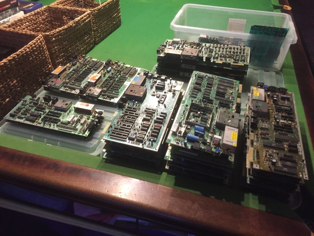
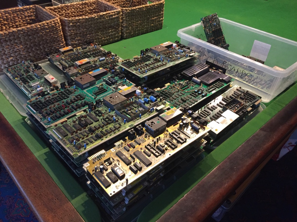
Alongside purchasing complete systems, over the past few years I’ve also accumulated a large quantity of incomplete circuit boards for “spares and repairs”, primarily from Commodore computers (VIC-20, VIC-20CR, C64, C64C, C16, Plus/4, C128, etc).
I got these for cheap in various job lots, with the intention of fixing up as many as possible and selling the working ones on for those who needed a fully-tested board (for swapping into a system, for use as a test board, etc). This meant I could focus on my favourite part of my work – the electronics restoration – without having to worry about case and keyboard cleaning, which is fun but can get quite tedious; also, a reliable supply of original spare parts from irreparable boards.
I recently finished my restoration of the salvageable boards, which has taken a VERY long time (bit by bit for the past year or so) because of both the quantity of the boards and the amount of work involved in testing, repairing, and cleaning each one.
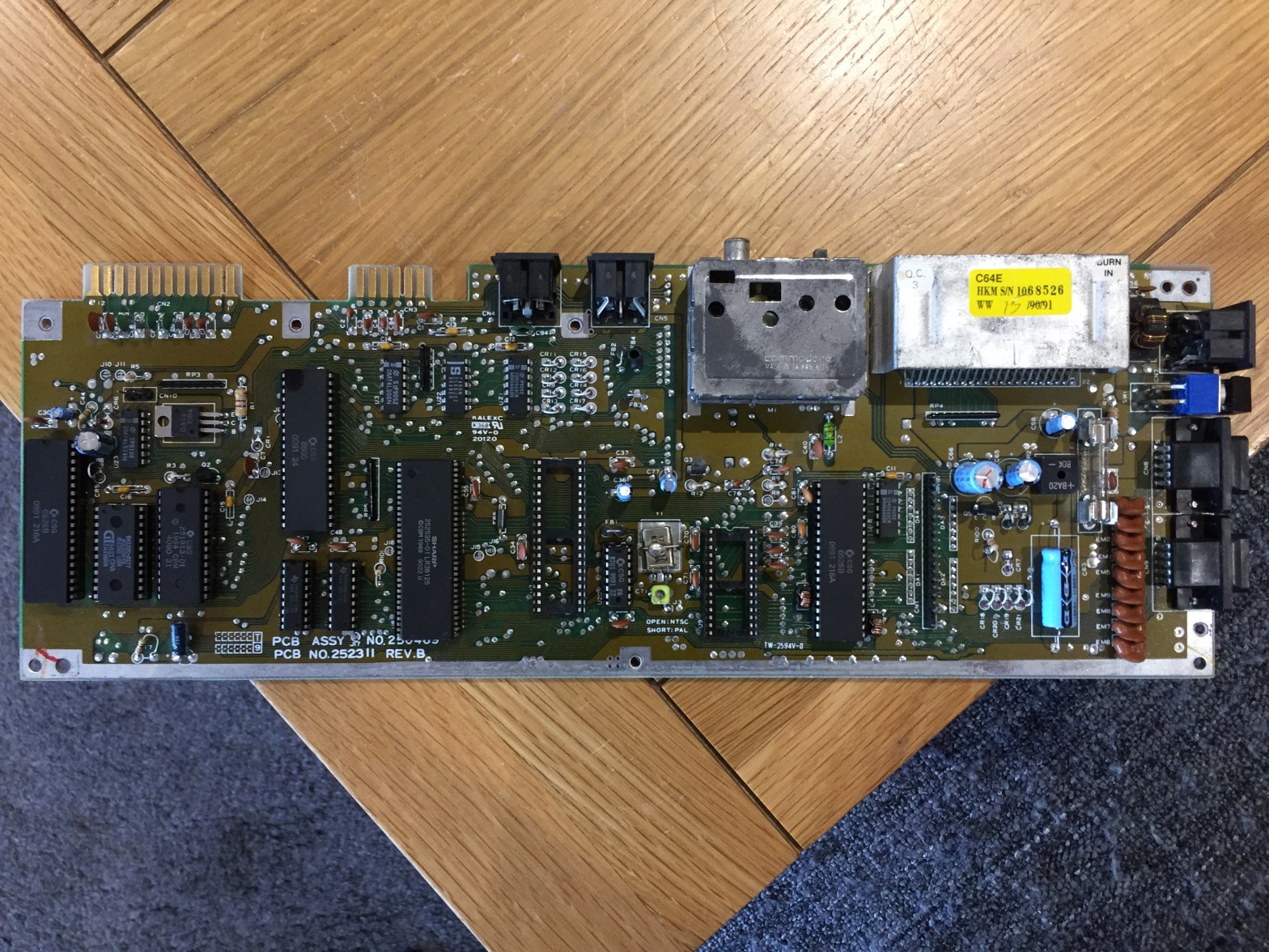
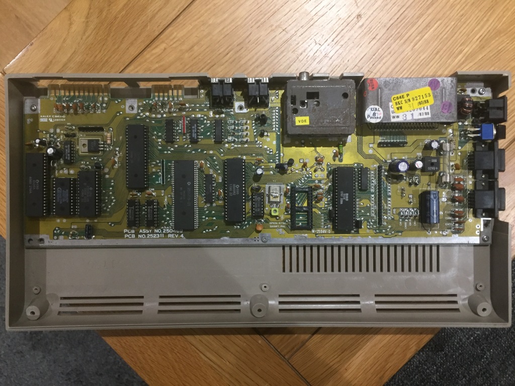
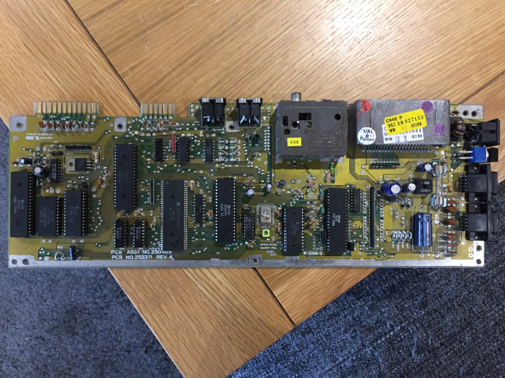
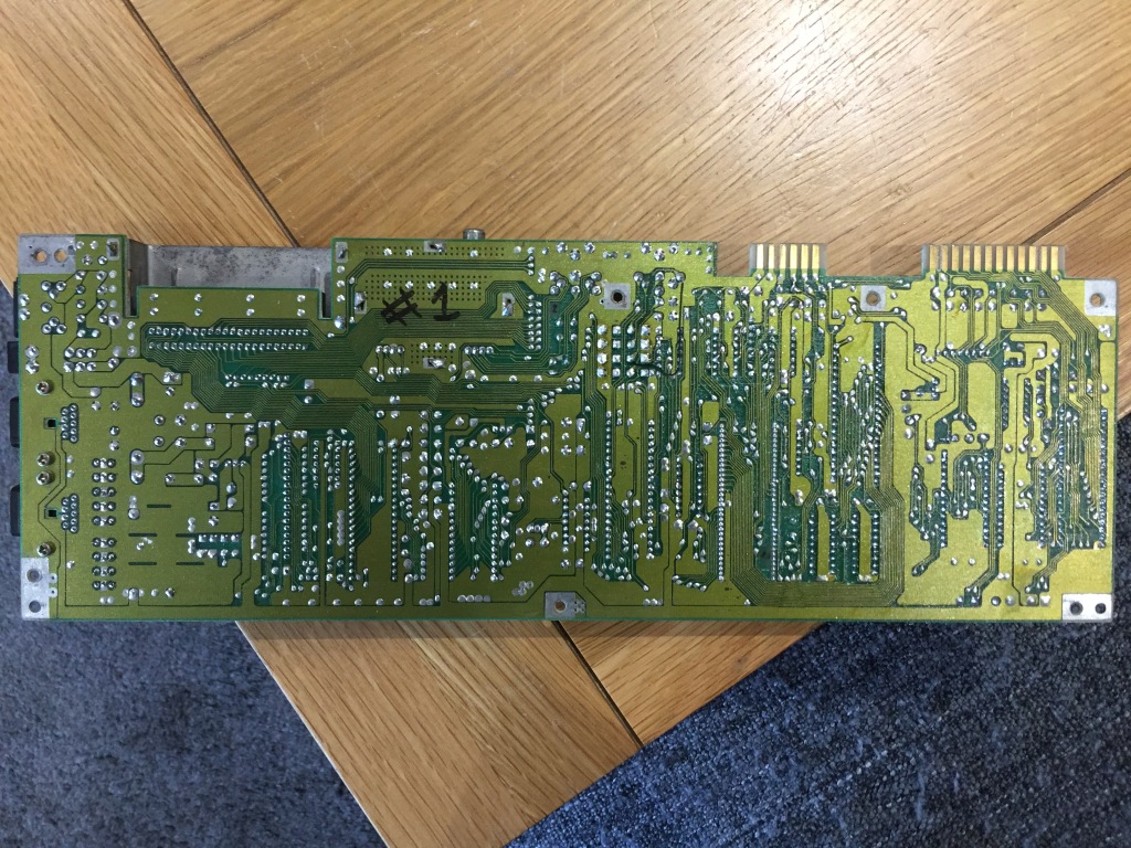
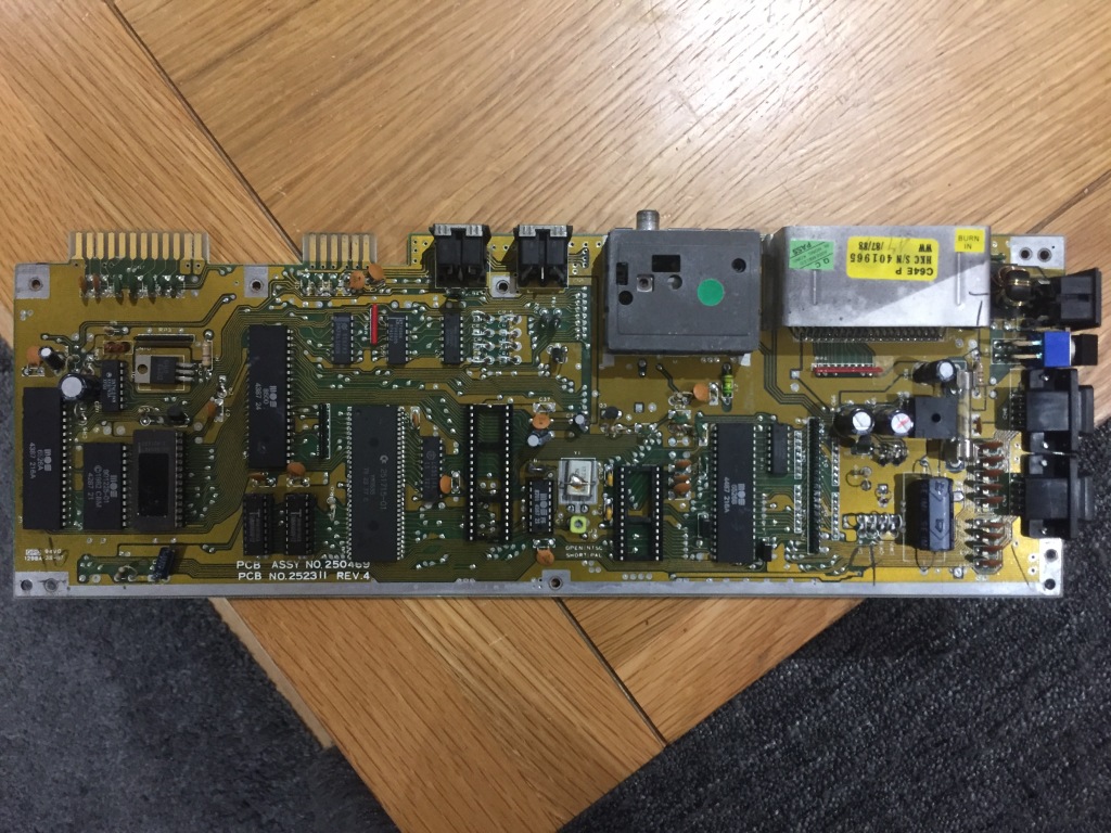
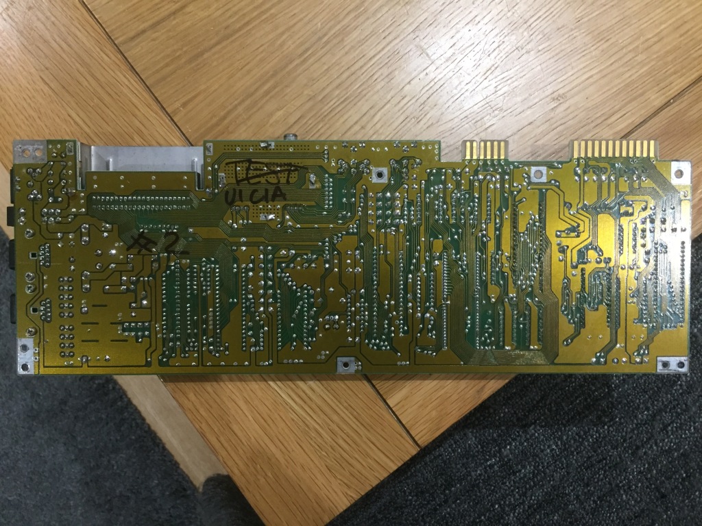
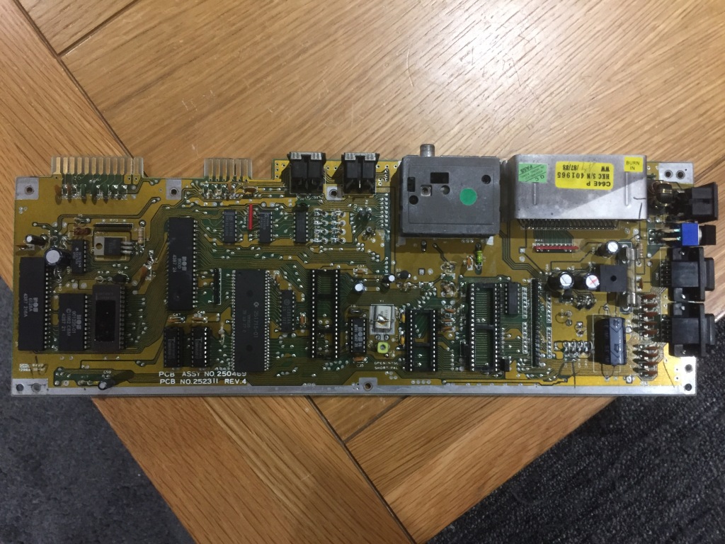
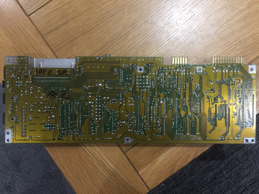
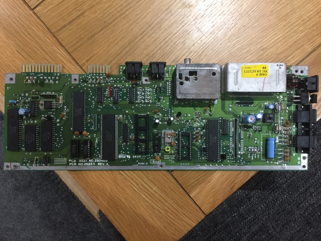
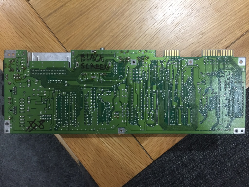
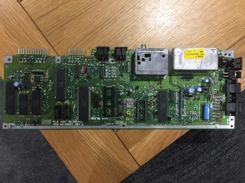
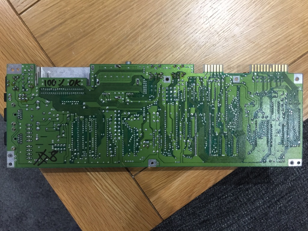
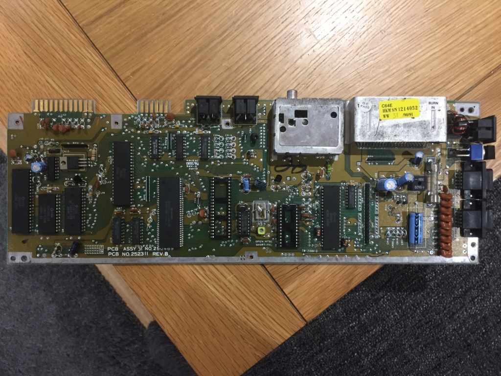
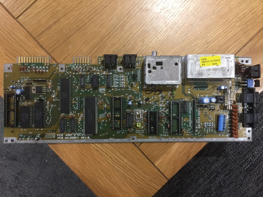
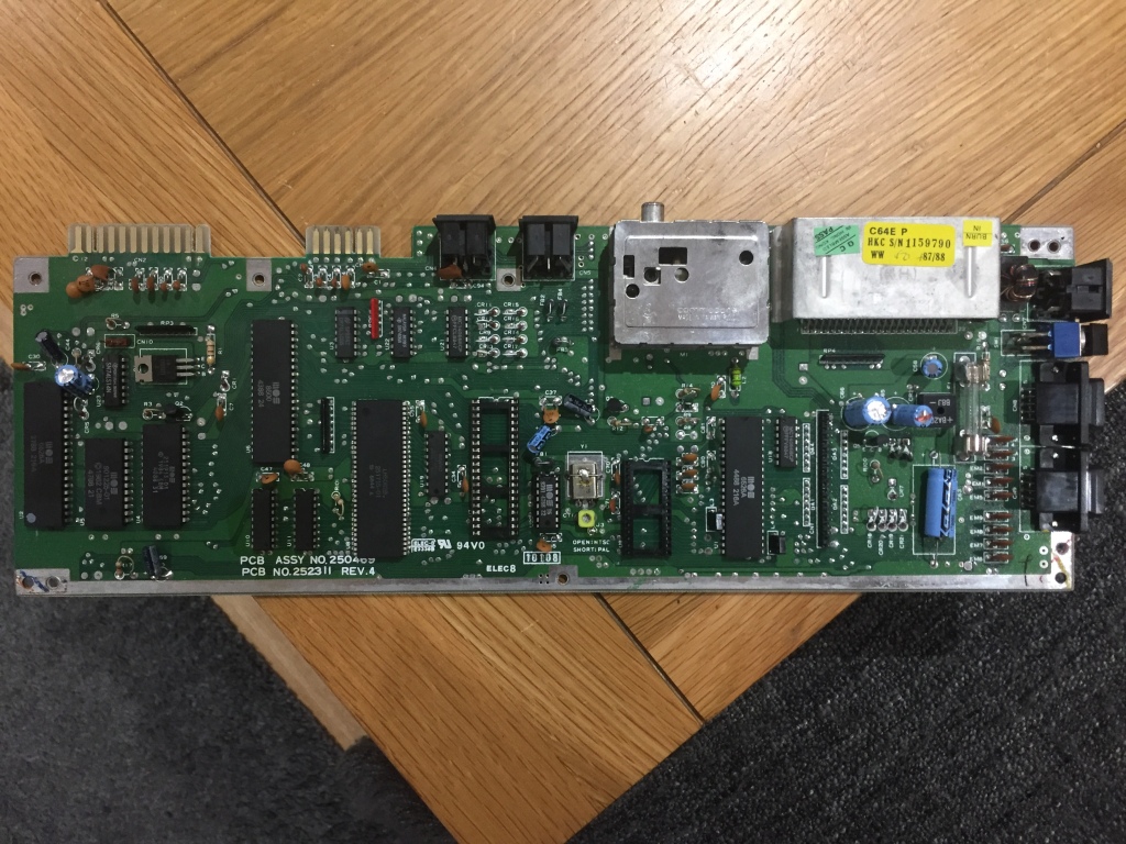
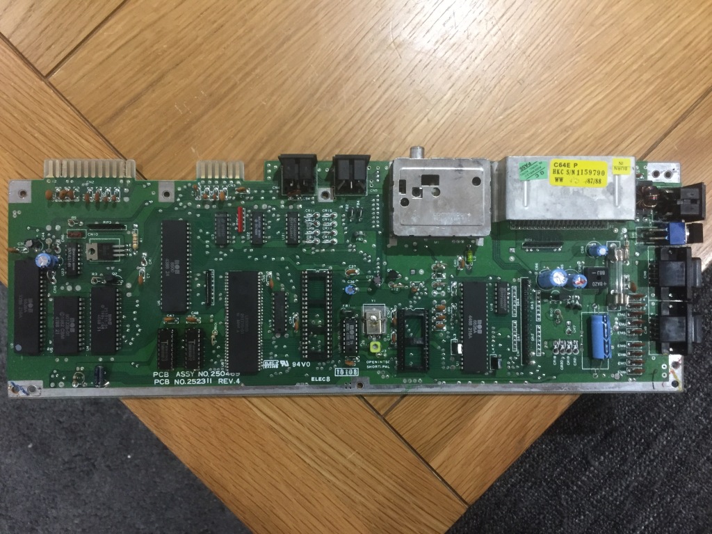
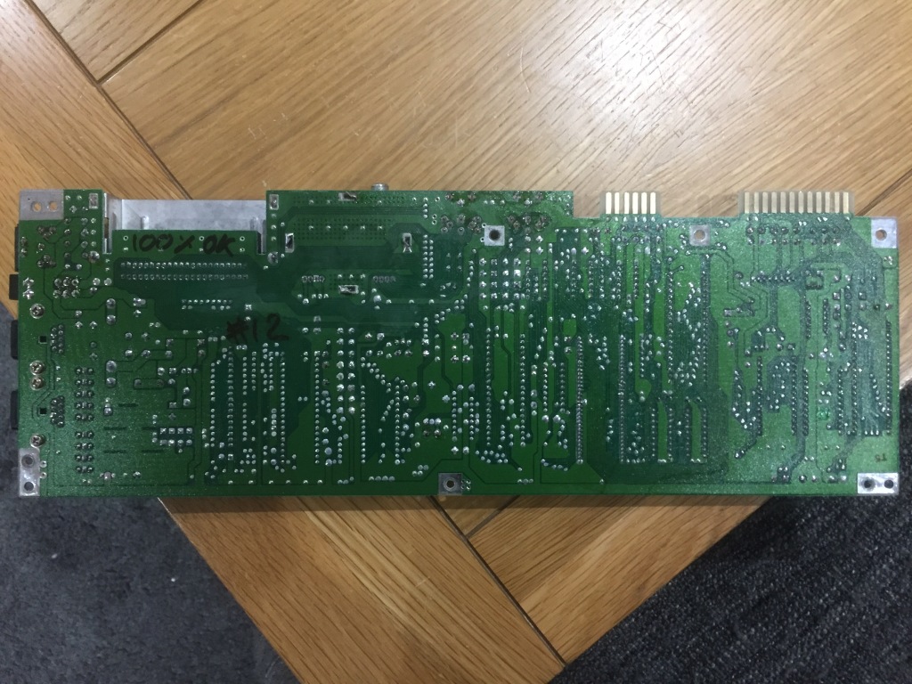
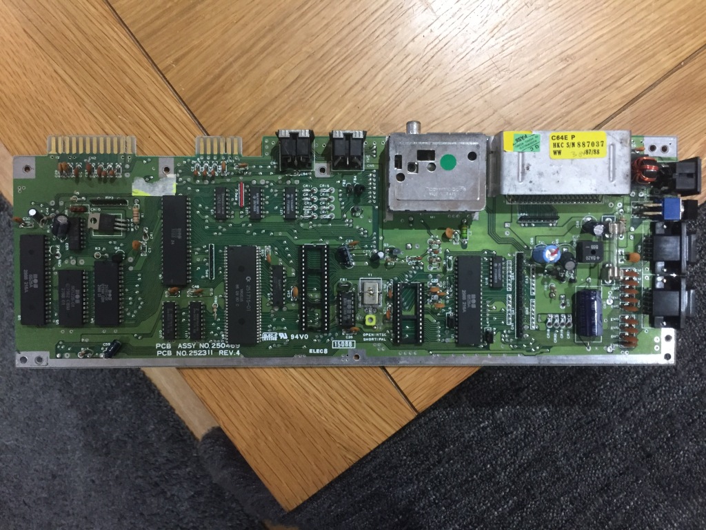
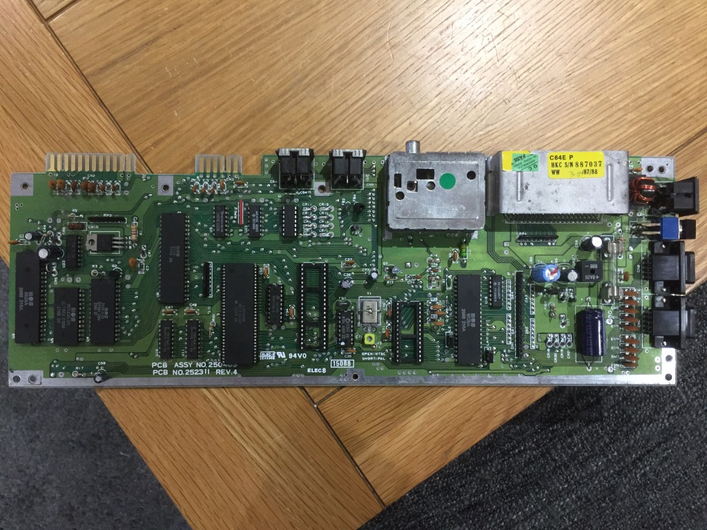
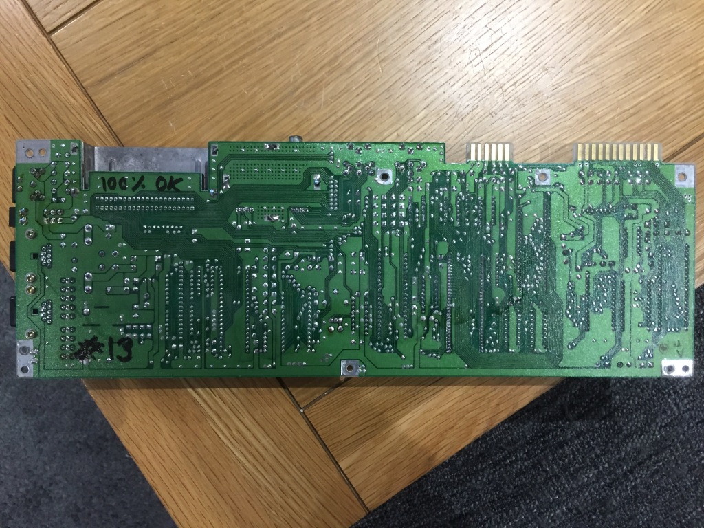
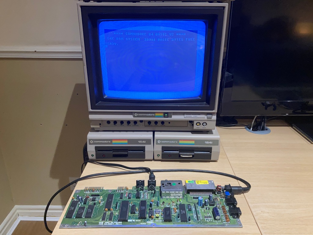
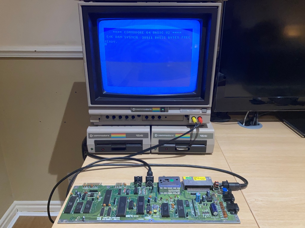
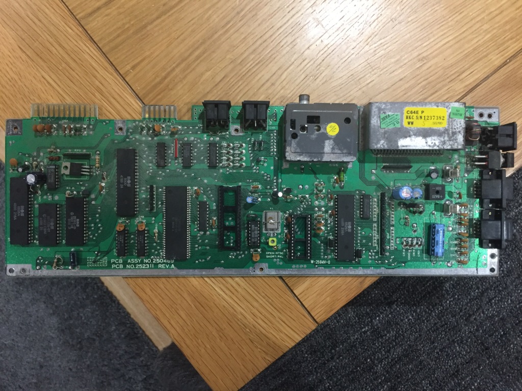
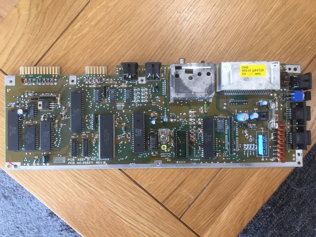
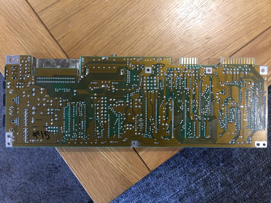
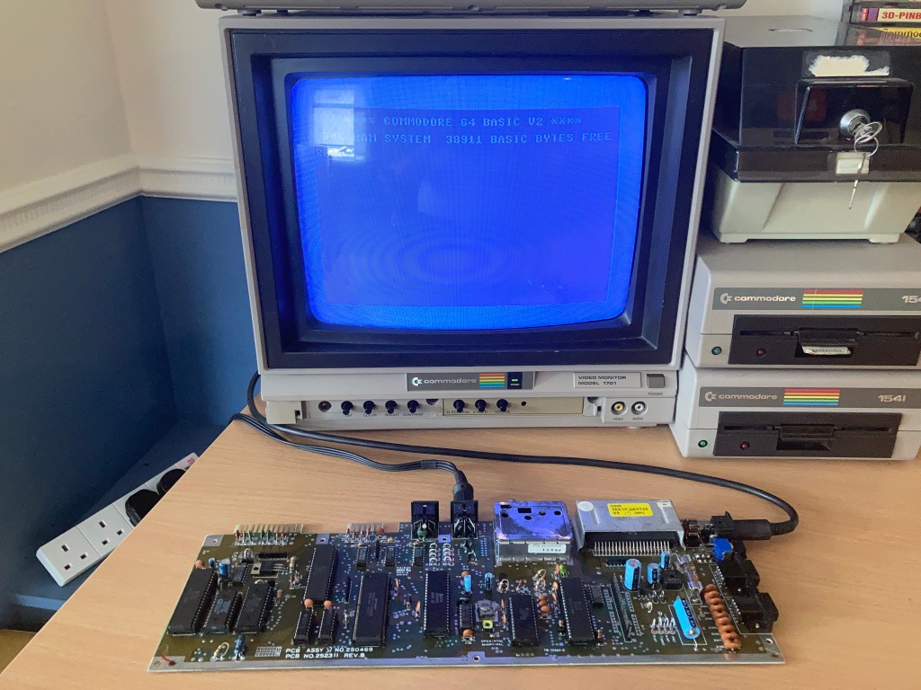
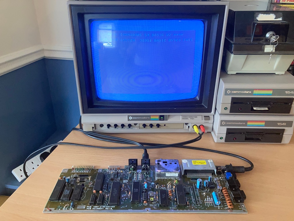
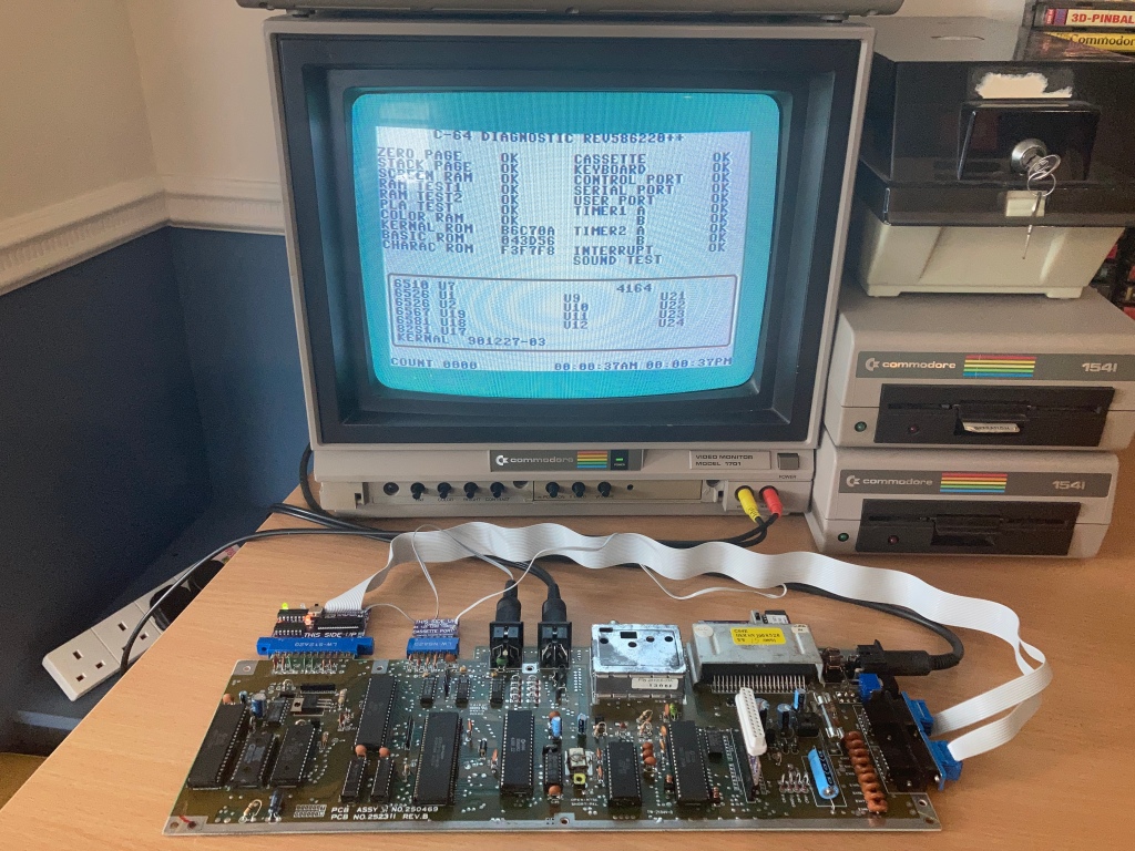
This article focuses on a set of C64 boards I worked on, specifically a large number of ASSY 250469 boards – a late revision shortboard which followed the ASSY 250466.
Commodore 64 250469 Board #1
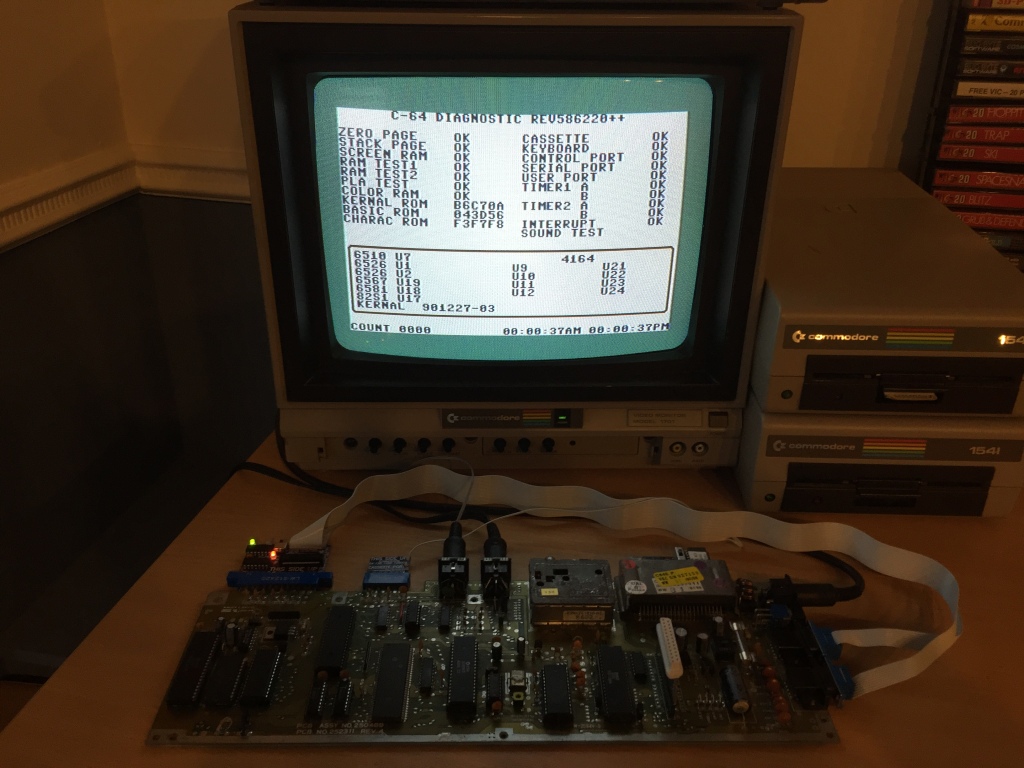
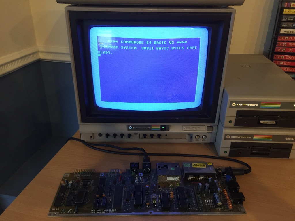
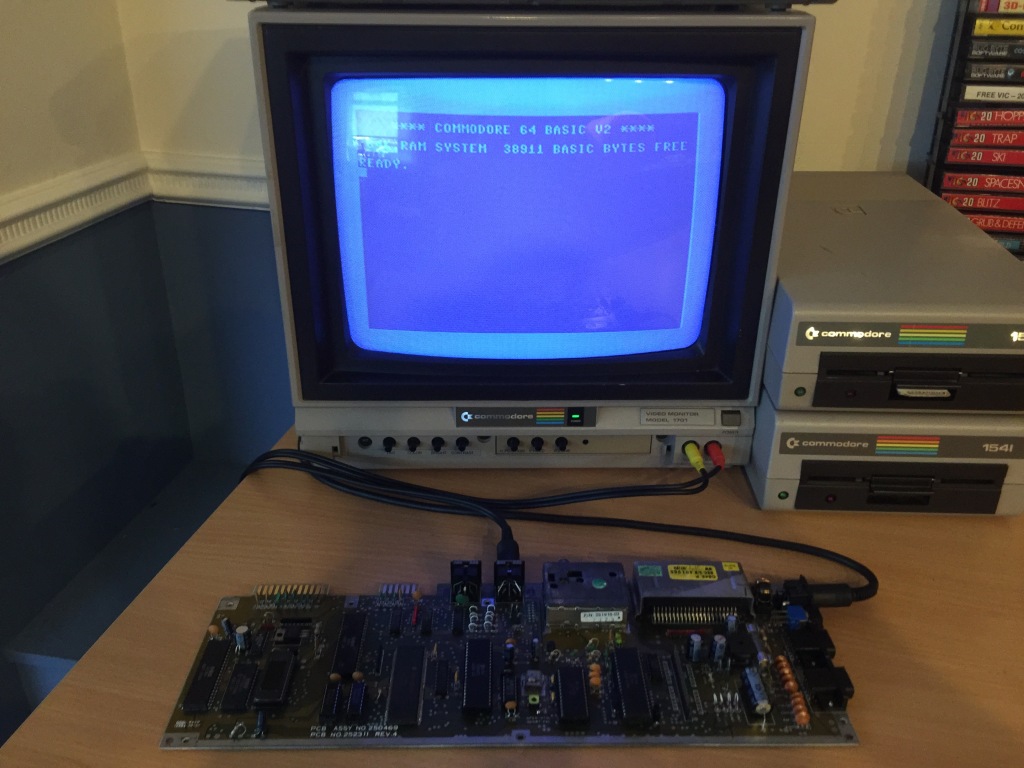
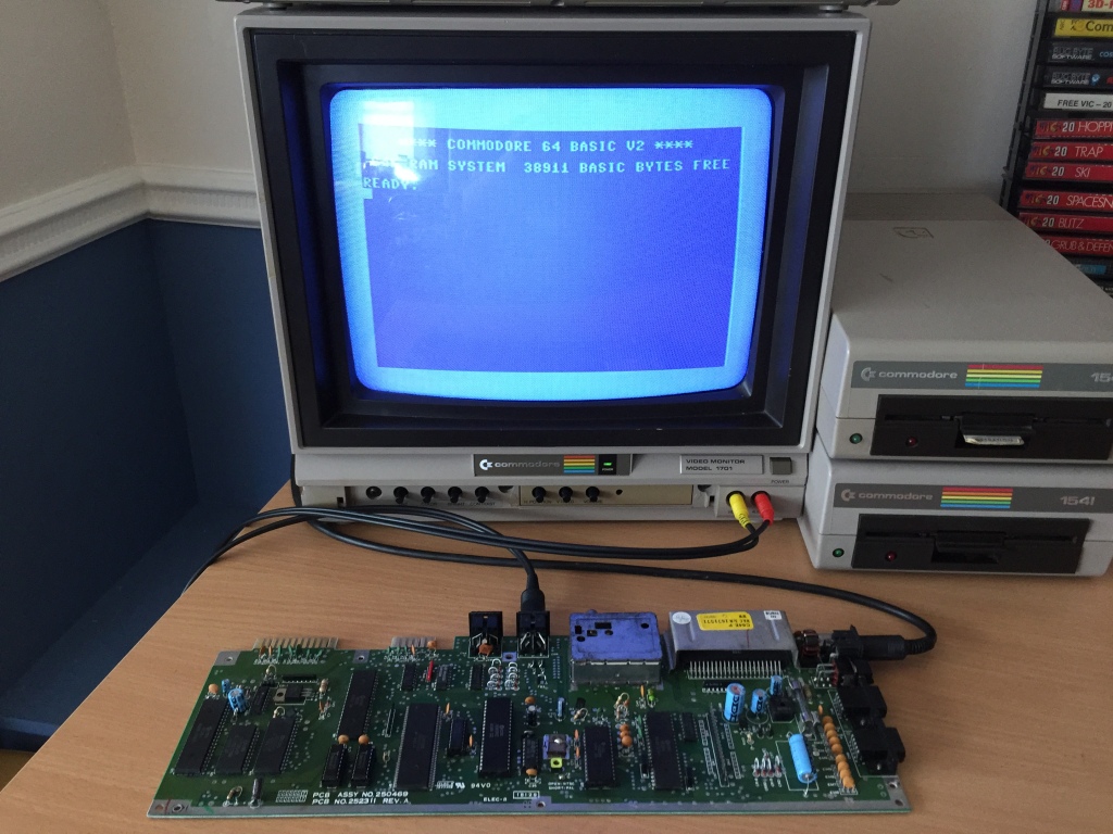
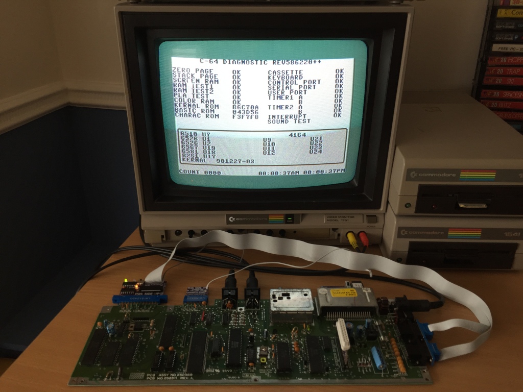
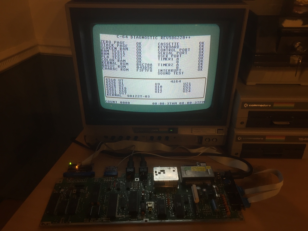
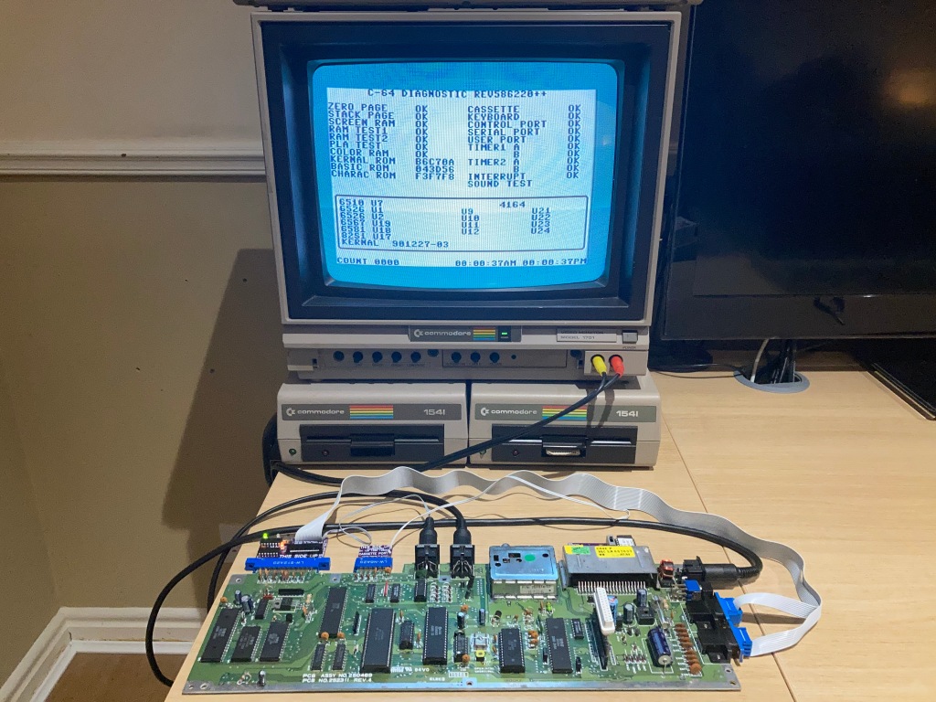
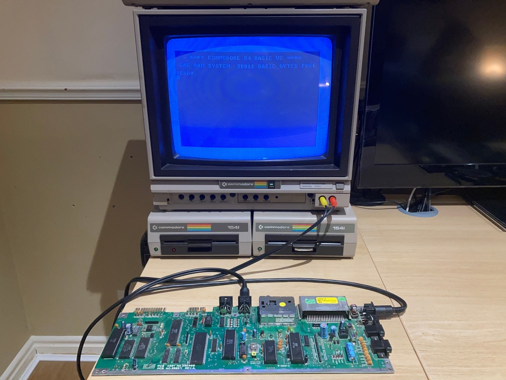
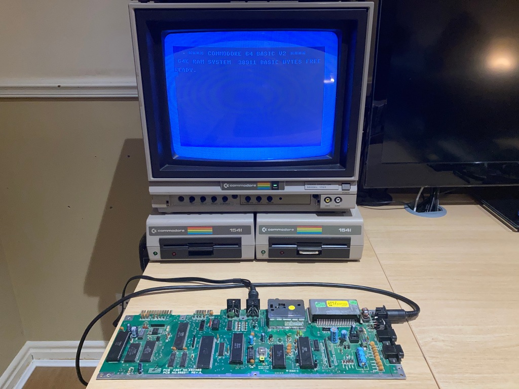
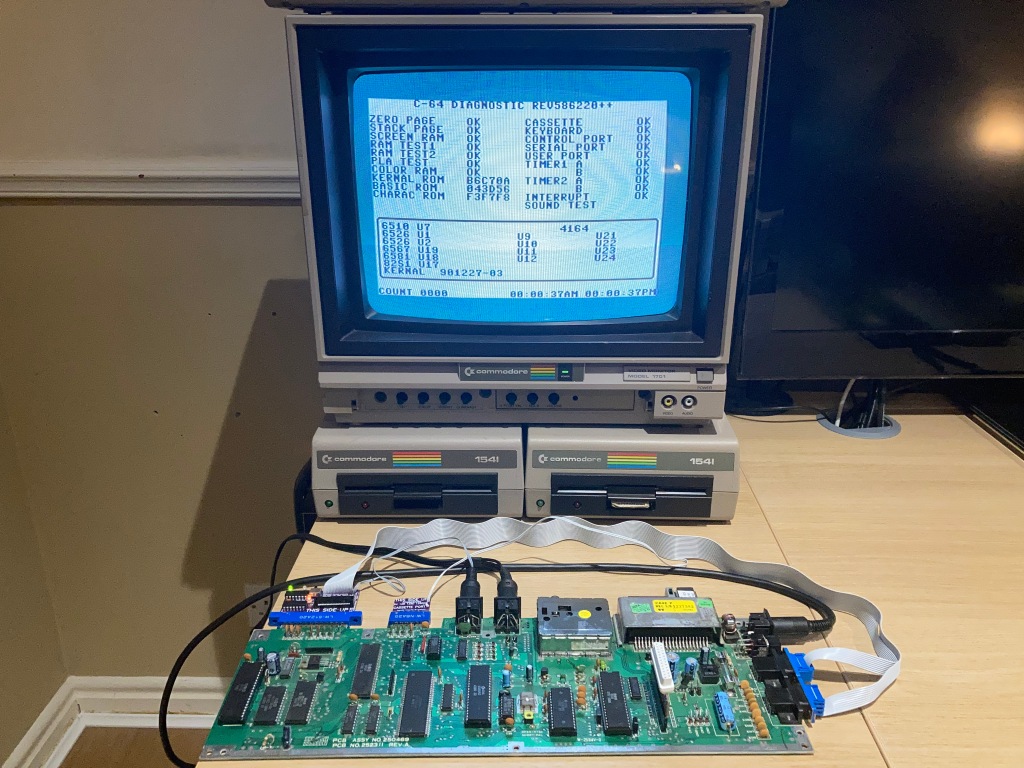
The first board is my Commodore 64C test board, which I use for testing ICs from the C64C to verify that they are working correctly.
Only the VIC-II (U7), SID (U9), and 8701 (U20) were socketed from the factory, and the two 41464 DRAM ICs (U10 and U11) had been socketed by the previous owner – with two new-old-stock 41464 DRAM ICs installed (available to buy from Retroleum) the board originally seemed to work fine. I socketed all of the other main ICs (except for the 64-pin SuperPLA) allowing me to test as many ICs as possible.
Unlike the earlier Commodore 64 longboards which all used eight 64K-by-1bit 4164 DRAM ICs, the ASSY 250469 shortboards (as used in the C64C, C64G, and C64 “Aldi”) uses two 64K-by-4bit 41464 DRAM ICs as a cost-saving measure.
I always use high-quality double-sided sockets, which are more reliable than cheap single-sided sockets as they contact the IC legs on both sides – a lot of people push the use of turned-pin sockets, but I don’t like using them as they make swapping ICs difficult, they are difficult to desolder, and they are visibly obviously non-standard.
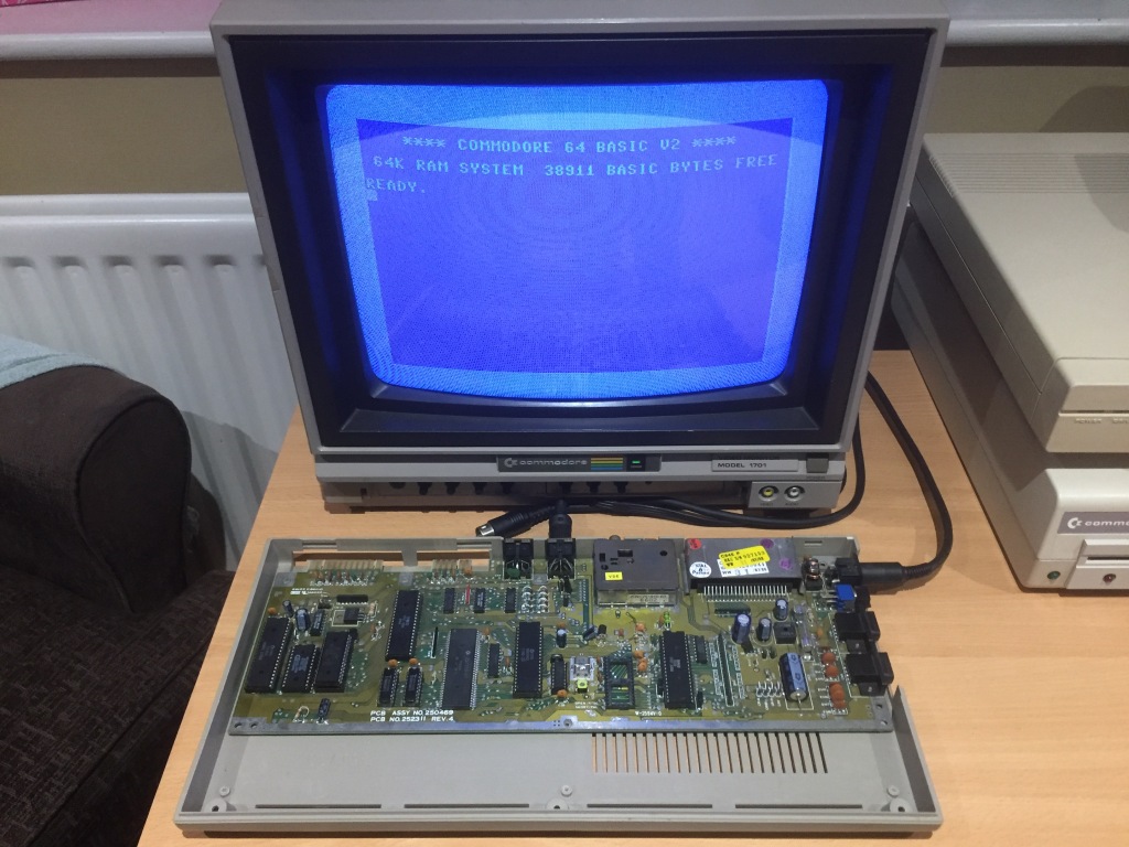
Then, one fateful day, I plugged my cassette port loopback dongle from my loopback harness in backwards and turned the machine on. Bad things ensued.
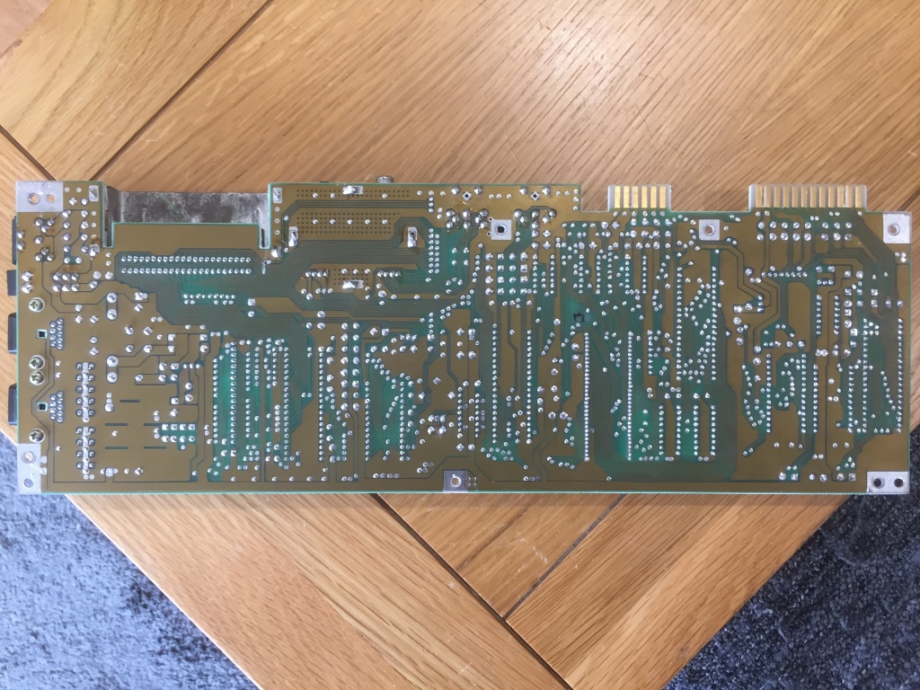
The internal fuse blew out immediately, and the computer wouldn’t boot up. When I pulled the board for further inspection, I noticed that one of the traces near the serial port connector on the underside of the PCB had burned up quite spectacularly.
I installed a spare fuse of the correct type and bridged the broken trace with a length of wrapping wire, then tested the board again – it still booted up OK (with flashing cursor and correct amount of RAM showing), but it failed the serial port test with a diagnostic cartridge and loopback harness installed and wouldn’t load from a disk drive (it would fail with a “?DEVICE NOT PRESENT” error).
Serial port problems are often due to failures with the Schmitt-trigger inverter (74LS14) which handles receiving bus signals, or the output driver (7406) which handles transmitting bus signals.
IC failures often lead to gates shorting or pulling on inputs or outputs, which draws more current, which increases die and package temperature – this can range from a subtle difference to something that could quickly burn your finger (i.e. RAM ICs damaged by overvoltage). Therefore, I used my IR thermometer to measure the temperature of all of the soldered ICs, to check for any outliers – I noticed that the 7406 at U22 (which should run cool) got very hot shortly after startup.
The 7406 is used as a buffer to drive the serial port output lines, and could be damaged if its outputs were shorted. I therefore removed the original IC using my desoldering station (a Duratool D00672) and tested it using my MiniPro TL866II, and it had indeed failed. I installed a socket (allowing the quick removal of ICs (i.e. for testing) without the need for rework) and fitted a new-old-stock 7406 IC (available to buy from Retroleum), but the serial port test still failed, and the 7406 still got warm.
The fact that the new 7406 was still getting warm indicated that its outputs were pulling heavy current (up to 50mA per pin) due to low impedance. This likely pointed to a problem with the serial port protection circuit.
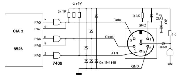
On most Commodore 64 boards, the serial port has a set of diodes between each output line and both the supply rail and ground, to try and limit damage when in case the port is plugged in incorrectly. If any of these diodes have failed, this can prevent the computer from transmitting correctly over the serial port.
I checked the diodes in question (CR9 and CR11-CR17, all 1N4148) in-circuit using the diode test function of my multimeter, and several of them were measuring inconsistently. The full set had obviously experienced a lot of stress, so I decided to replace the whole lot – they’re not an expensive part. I used an equivalent diode, the 1N914.
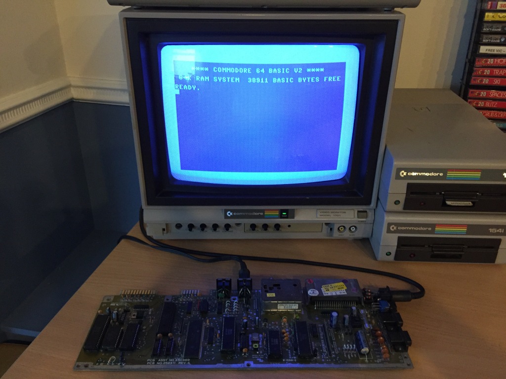
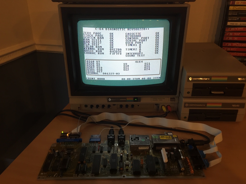
After this, the board then passed all tests with a diagnostic cartridge and loopback harness installed, including the serial port test that had failed previously.
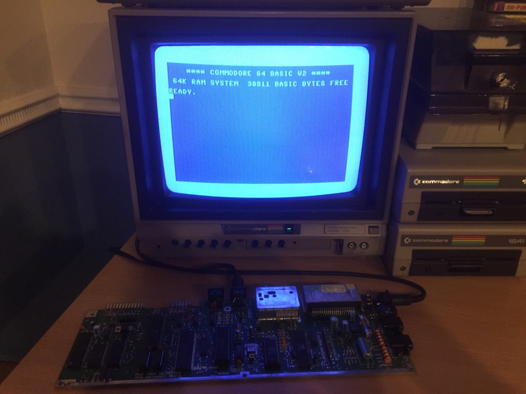
Fully tested with diagnostic harness; composite video output OK; luma/chroma video output OK; audio output OK; cleaned ports, power switch, and edge connectors.
Commodore 64 250469 Board #2
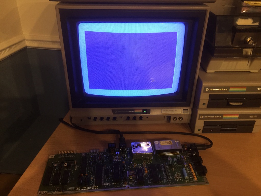
The second board would output video but would not boot up correctly, displaying only a blank black screen with no border or text.
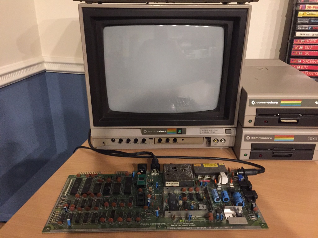
In the C64, a black screen fault is a common failure mode which can indicate all kinds of problems: typically, a missing or improper signal, a data or address bus conflict, an addressing problem, or a stack page fault, all of which can be caused by a power issue or a failed IC. Most of the ICs on the board are connected to the data or address bus, so there are a large number of potential problems that need to be worked through.
The first thing to check with any repair is that power is being correctly received on the board, which may indicate a problem with the power socket, power switch, or fuse – I checked for 9Vac and 5Vdc at the user port, and both were OK; on the ASSY 250469 mainboard, there is no 12Vdc supply to the VIC-II to check.
A constant reset can also cause a black screen – I checked the reset signal at the user port and it worked as expected, staying low (around 0Vdc) for about a second at power on, then going high (around 5Vdc).
I checked for physical damage on the board which could be causing connection problems, including scratches or cold solder joints, but everything seemed OK.
I also checked for signs of previous rework which could indicate a potential problem (flux residue, non-factory sockets, etc) – the 28-pin Kernal/BASIC ROM had been socketed and replaced with an EPROM, but the socket installation seemed fine and the EPROM itself tested OK as a standard C64C ROM in another board.
I reseated all of the socketed ICs and cleaned all sockets, ports, and switches with contact cleaner, however there was still no change in symptoms.
I tried the machine using a dead-test cartridge, which can indicate potential hardware issues (i.e. bad ROM, bad RAM) – however, there was no change in symptoms. I tried the same with a diagnostic cartridge, with the same result.
I used my IR thermometer to measure the temperature of all of the soldered ICs, to check for any outliers. IC failures often lead to gates shorting or pulling on inputs or outputs, which draws more current, which increases die and package temperature – this can range from a subtle difference to something that could quickly burn your finger.
With this, I noticed that both 41464 DRAM ICs (U10 and U11), which should run cool, got very hot shortly after startup – these RAM ICs are very sensitive to overvoltage from failing PSUs, so its quite common for boards to have these kind of failure modes.
I therefore removed the two original ICs using my desoldering station (a Duratool D00672) and tested them in my RAM tester, and both had indeed failed. I installed two sockets (allowing the quick removal of ICs without the need for rework), and fitted two new-old-stock 41464 DRAM ICs (available to buy from Retroleum).
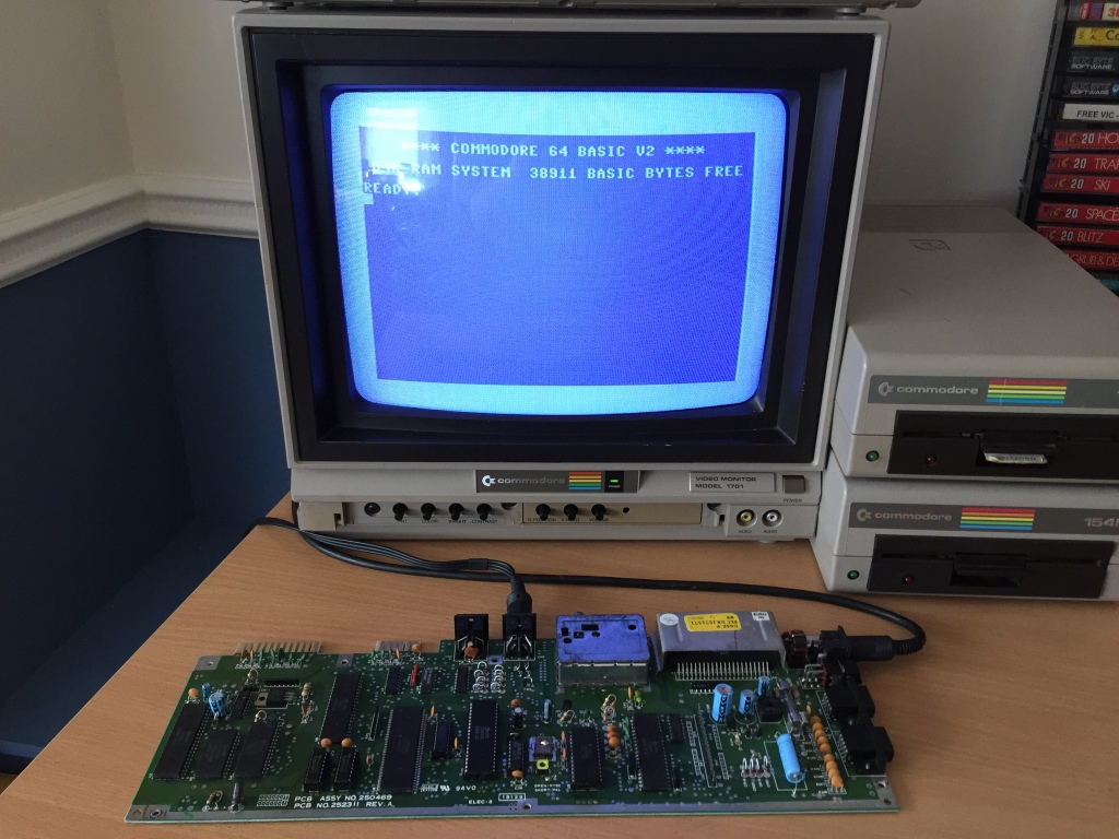
After this, I tested the board again and booted up OK for the first time (with flashing cursor and correct amount of RAM showing).
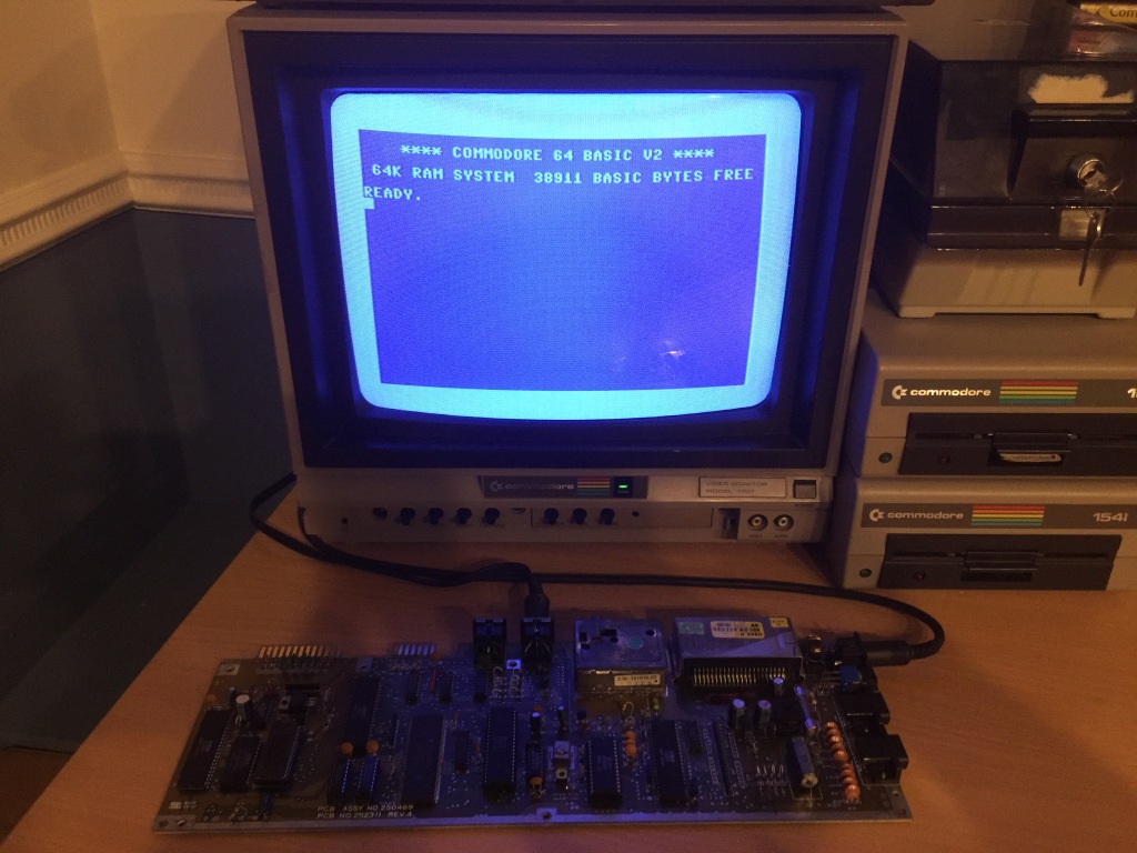
However, it wouldn’t load from a disk drive (giving a “?DEVICE NOT PRESENT” error), and would fail the serial port test with a diagnostic cartridge and loopback harness installed.
The diagnostic cartridge indicated the 6526 CIA (Complex Interface Adaptor) IC at U1 being at fault, as this is responsible for controlling the serial interface – there is also the Schmitt-trigger inverter (74LS14) which handles receiving bus signals, and the output driver (7406) which handles transmitting bus signals.
I removed the U1 CIA IC and tested it in another board, and it had indeed failed. I installed a socket and fitted a known-good spare 6526 IC, and the board now passed all tests with the diagnostic cartridge and loopback harness installed.
Fully tested with diagnostic harness; composite video output OK; luma/chroma video output OK; audio output OK; cleaned ports, power switch, and edge connectors.
Commodore 64 250469 Board #3
The third board was missing its fuse and was completely missing both RAM ICs (U10 and U11) – I fitted a fuse of the correct type, installed sockets on the two RAM locations (allowing the quick removal of ICs without the need for rework), and fitted two new-old-stock 41464 DRAM ICs (available to buy from Retroleum).
After testing, the board would output video but would not boot up correctly, displaying only a blank black screen with no border or text.
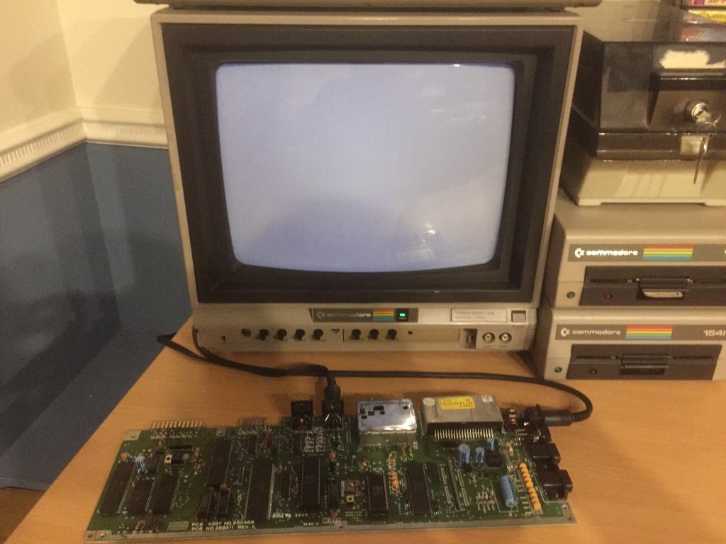
In the C64, a black screen fault is a common failure mode which can indicate all kinds of problems: typically, a missing or improper signal, a data or address bus conflict, an addressing problem, or a stack page fault, all of which can be caused by a power issue or a failed IC. Most of the ICs on the board are connected to the data or address bus, so there are a large number of potential problems that need to be worked through.
The first thing to check with any repair is that power is being correctly received on the board, which may indicate a problem with the power socket, power switch, or fuse – I checked for 9Vac and 5Vdc at the user port, and both were OK; on the ASSY 250469 mainboard, there is no 12Vdc supply to the VIC-II to check.
A constant reset can also cause a black screen – I checked the reset signal at the user port and it worked as expected, staying low (around 0Vdc) for about a second at power on, then going high (around 5Vdc).
I checked for physical damage on the board which could be causing connection problems, including scratches or cold solder joints, but everything seemed OK.
I also checked for signs of previous rework which could indicate a potential problem (flux residue, non-factory sockets, etc) – both RAM ICs had obviously been removed, but there was no visible damage before I installed the RAM sockets, and I checked continuity across all connections on both RAM ICs using my multimeter, and everything was OK.
I reseated all of the socketed ICs and cleaned all sockets, ports, and switches with contact cleaner, however there was still no change in symptoms.
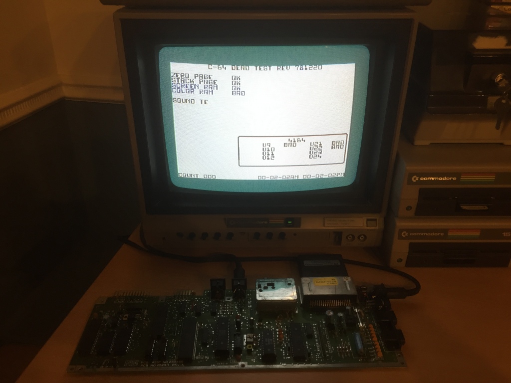
I tried the machine using a dead-test cartridge, which can indicate potential hardware issues (i.e. bad ROM, bad RAM). I got a variety of different results which seemed to change each time the system was started up, including: a single screen flash (indicating a stuck data bit); a blue border screen; and a normal dead-test screen with flickering text colours – the colour RAM test would fail (RAM ICs at U9, U21, and U22 were also indicated as being at fault), then the system would crash to a garbage screen or the single screen flash.
The flickering text and the colour RAM test failure was a clear indication of the probable fault – the indicated RAM failures (U9, U21, and U22) were likely a red herring, being caused by issues with their associated data lines.
On this version of the ASSY 250469 board (REV A), the colour RAM is its own IC (a 2114 SRAM IC at U19) – on the last version of the board (REV B), the colour RAM is integrated into the 64-pin SuperPLA IC (U8), which is also responsible for all kinds of control and addressing in the Commodore 64.
I removed the 2114 colour RAM IC and tested it in another board, and it had indeed failed. I installed a socket and fitted a new-old-stock 2114 SRAM IC (available to buy from Retroleum), and the board booted up OK for the first time (with flashing cursor and correct amount of RAM showing).
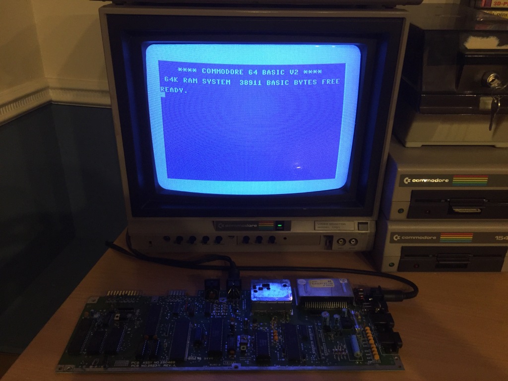
It also passed all tests with a diagnostic cartridge and loopback harness installed.
Fully tested with diagnostic harness; composite video output OK; luma/chroma video output OK; audio output OK; cleaned ports, power switch, and edge connectors.
Commodore 64 250469 Board #4
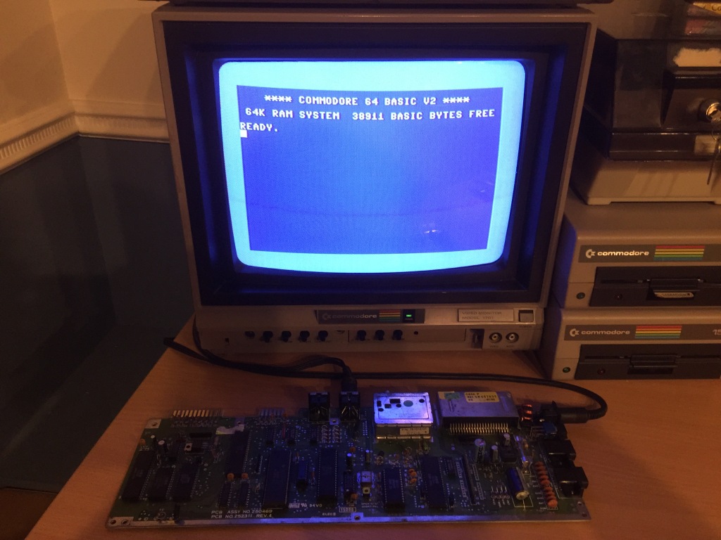
The fourth board booted up OK (with flashing cursor and correct amount of RAM showing).
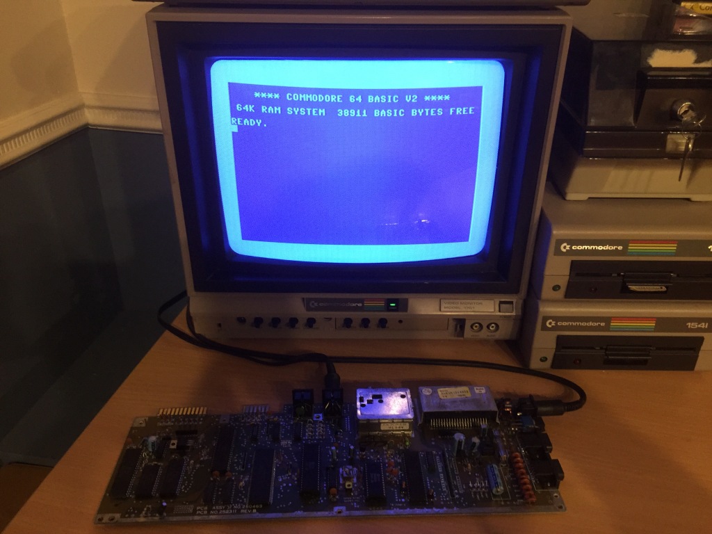
However, with a diagnostic cartridge and loopback harness installed it failed on cassette, serial port, and user port tests, indicating both the U1 and U2 CIAs as being at fault.
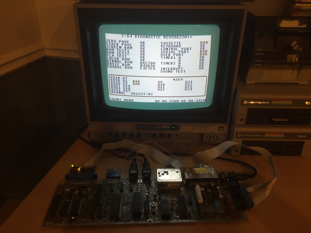
I removed both 6526 CIA ICs (U1 and U2) using my desoldering station (a Duratool D00672) and tested them in my C64C test board, and (surprisingly) both seemed to be working fine. I installed a set of sockets (allowing the quick removal of ICs without the need for rework) and refitted the original ICs.
Alongside the 6526 CIAs being at fault, as these are responsible for controlling the faulty interfaces, there is also the Schmitt-trigger inverter (74LS14) which handles receiving bus signals, and the output driver (7406) which handles transmitting bus signals.
I connected up a known-good 1541 disk drive, and it would not reset when the board was powered on, meaning that the serial reset signal was not being generated correctly.

This signal, along with all the other serial output lines, is buffered by the 7406 inverter at U22, indicating that this was a probable failure point.
I removed U22 (7406) and tested it using my MiniPro TL866II – it had indeed failed (on gates 2, 3, 5, and 6), so I installed a socket and replaced it with a new-old-stock 7406 IC (available to buy from Retroleum). After this, the board now seemed to pass all tests with the diagnostic cartridge and loopback harness installed.
Fully tested with diagnostic harness; composite video output OK; luma/chroma video output OK; audio output OK; cleaned ports, power switch, and edge connectors.
Commodore 64 250469 Board #5
The fifth board would output video but would not boot up correctly, displaying only a blank black screen with no border or text.
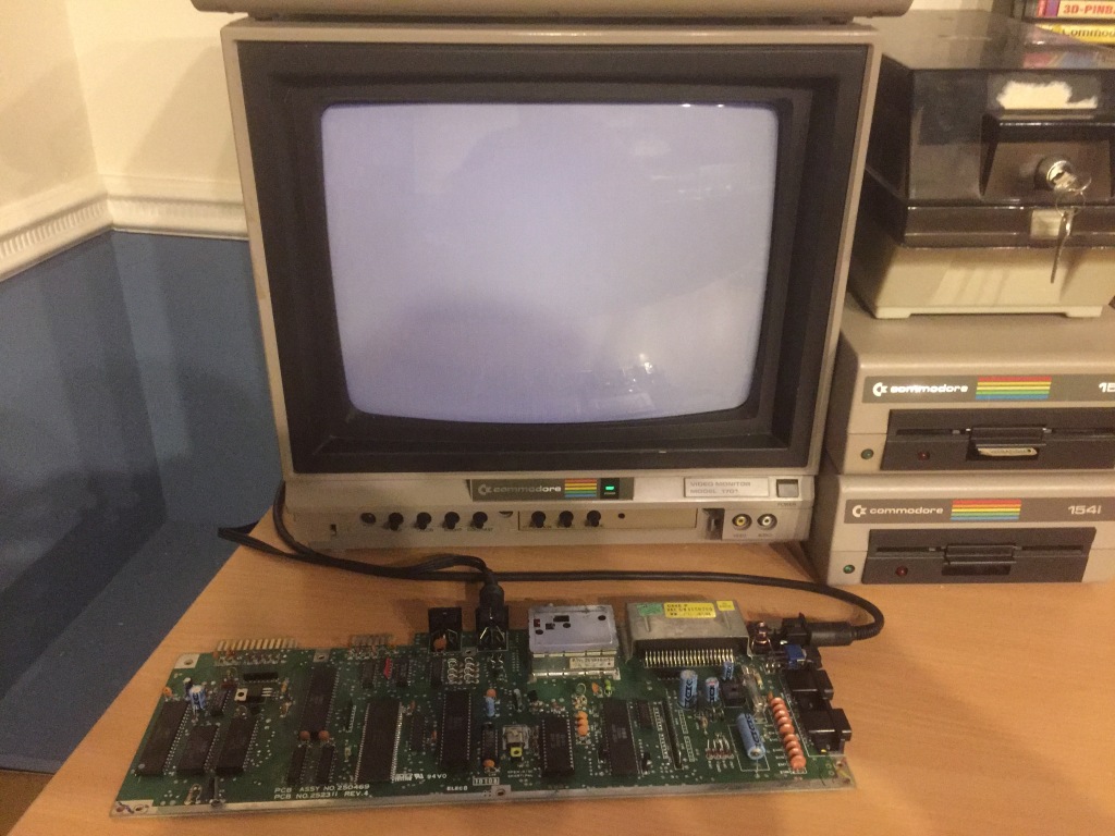
In the C64, a black screen fault is a common failure mode which can indicate all kinds of problems: typically, a missing or improper signal, a data or address bus conflict, an addressing problem, or a stack page fault, all of which can be caused by a power issue or a failed IC. Most of the ICs on the board are connected to the data or address bus, so there are a large number of potential problems that need to be worked through.
The first thing to check with any repair is that power is being correctly received on the board, which may indicate a problem with the power socket, power switch, or fuse – I checked for 9Vac and 5Vdc at the user port, and both were OK; on the ASSY 250469 mainboard, there is no 12Vdc supply to the VIC-II to check.
A constant reset can also cause a black screen – I checked the reset signal at the user port and it worked as expected, staying low (around 0Vdc) for about a second at power on, then going high (around 5Vdc).
I checked for physical damage on the board which could be causing connection problems, including scratches or cold solder joints, but everything seemed OK.
I also checked for signs of previous rework which could indicate a potential problem (flux residue, non-factory sockets, etc), but there was none.
I reseated all of the socketed ICs and cleaned all sockets, ports, and switches with contact cleaner, however there was still no change in symptoms.
I tried the machine using a dead-test cartridge, which can indicate potential hardware issues (i.e. bad ROM, bad RAM) – this consistently gave a single flash code, indicating a problem with data bit 7. According to the dead-test cartridge manual, the 41464 DRAM IC at U11 on this board revision is suspect as this is responsible for data bits 4-7.
I removed both 41464 DRAM ICs (U10 and U11) using my desoldering station (a Duratool D00672) and tested them in my C64C test board, and one had failed. I installed a pair of sockets (allowing the quick removal of ICs without the need for rework), refitted the working original RAM chip, and fitted a new-old-stock 41464 DRAM IC (available to buy from Retroleum). After this, the board seemed to boot OK for the first time (with flashing cursor and correct amount of RAM showing).
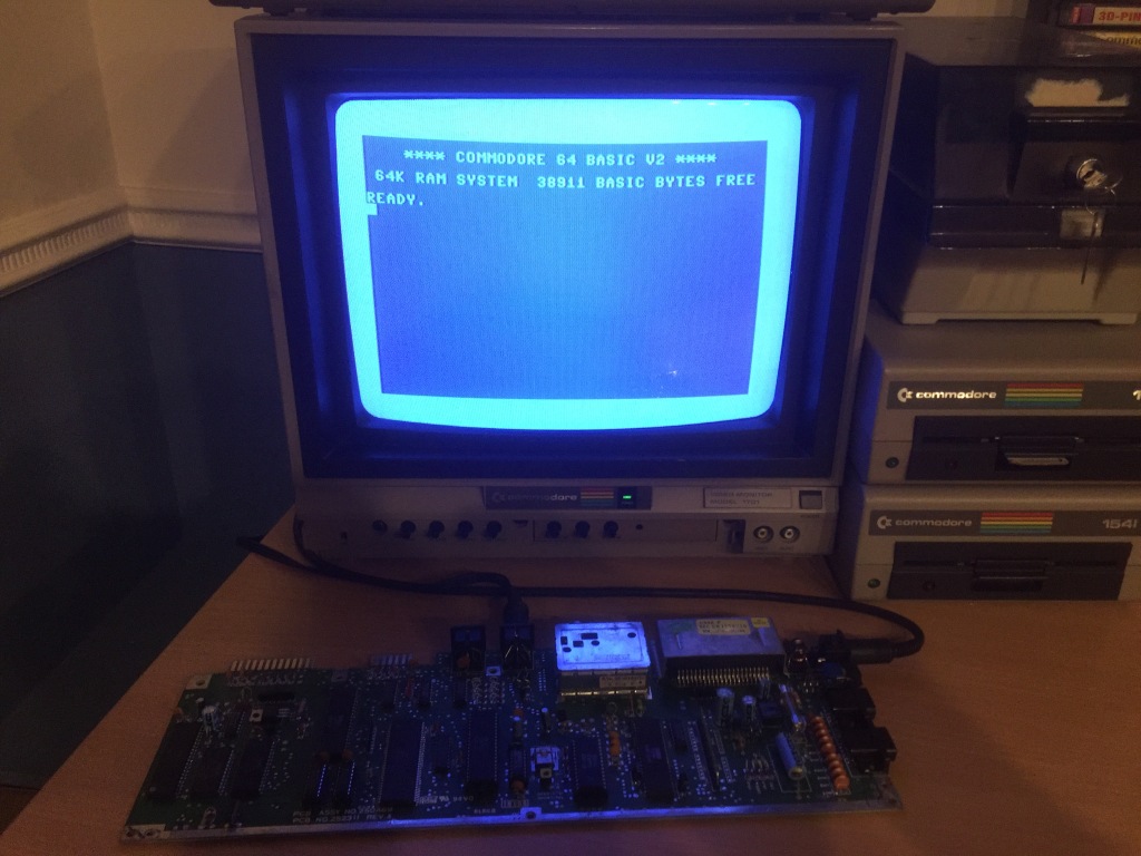
It also passed all tests with a diagnostic cartridge and loopback harness installed.
Fully tested with diagnostic harness; composite video output OK; luma/chroma video output OK; audio output OK; cleaned ports, power switch, and edge connectors.
Commodore 64 250469 Board #6
The sixth board would output video and boot to a normal startup screen (with flashing cursor and correct amount of RAM showing), but with shimmering text colours.
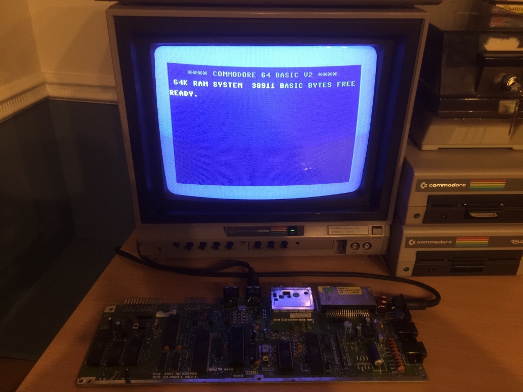
With a diagnostic cartridge installed, the text colours would still shimmer – the PLA test would fail, then either the test sequence would complete and start over, or the system would crash. The PLA (U17 in the early board, U8 in the short board) and several RAM ICs (U12 and U21-24 in the early board, U10 and U11 in the short board) were indicated as being at fault – the indicated RAM failures were likely a red herring, being caused by issues with their associated data lines.
I figured that the 64-pin SuperPLA was the probable culprit, so I removed it using my desoldering station (a Duratool D00672) – which is no mean feat as the IC is very large, the vias are very small, the pins are very close together, and it has a lot of ground plane connections – and tested it in my C64C test board, and it was OK. I installed a socket (allowing the quick removal of ICs without the need for rework) and refitted the original IC.
Upon reflection, the SuperPLA is a very uncommon failure point, so was unlikely to be at fault – the next most likely culprit was the colour RAM.
On this version of the ASSY 250469 board (REV A), the colour RAM is its own IC (a 2114 SRAM IC at U19) – on the last version of the board (REV B), the colour RAM is integrated into the 64-pin SuperPLA IC (U8).
I removed the 2114 colour RAM IC (U19) and tested it in another board, and it had indeed failed. I installed a socket and fitted a new-old-stock 2114 SRAM IC (available to buy from Retroleum), and the board still booted to a normal startup screen but now, instead of flashing coloured text, all the text (even on the cartridge screen) was a static grey.
The diagnostic cartridge tests still either failed on the PLA test, or crashed the system – therefore, there was no change in symptoms aside from the text colour.
The 4066 quad bilateral switch IC (U21) is also used to control character colours in the C64, so this was my next suspect. I removed the original IC, installed a socket, and tested the board using a new-old-stock 4066 IC (available to buy from Retroleum) – however, there was still no change in symptoms, so I refitted the original IC.
I then noticed that I’d made a mistake, previously: the new 2114 colour RAM IC (U19) had been fitted backwards. I amended this and retested the board, and now all of the text colour problems were resolved. This is why you should always check your work, twice!
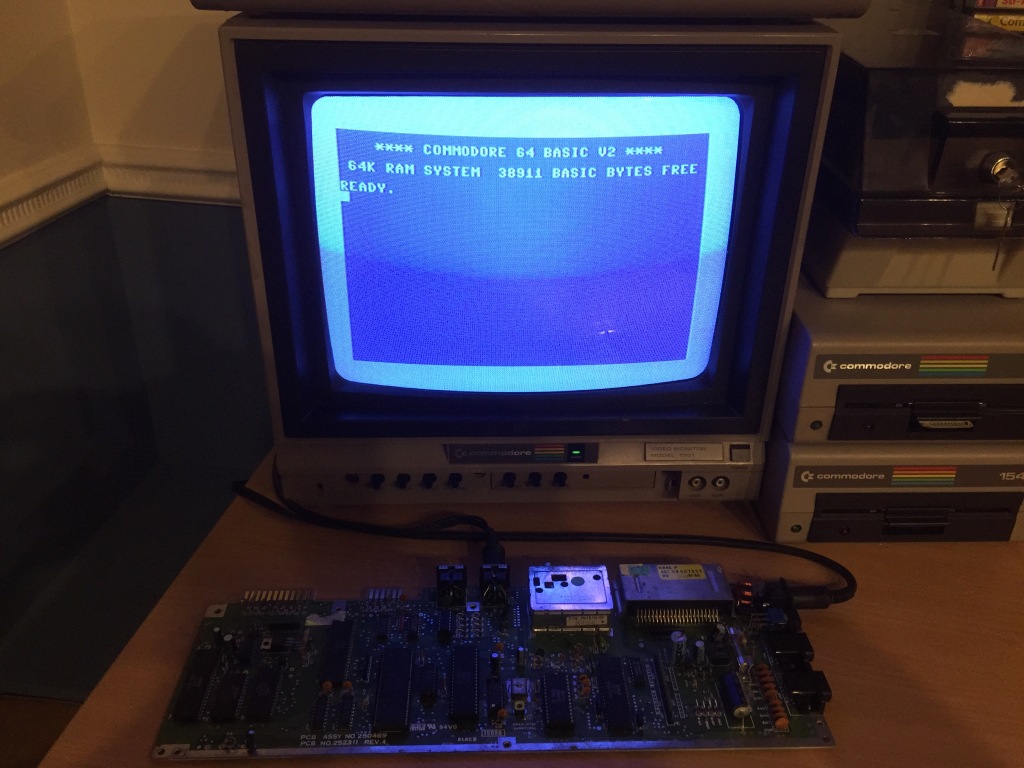
It also passed all tests with a diagnostic cartridge and loopback harness installed.
Fully tested with diagnostic harness; composite video output OK; luma/chroma video output OK; audio output OK; cleaned ports, power switch, and edge connectors.
Commodore 64 250469 Board #7
The seventh board booted OK (with flashing cursor and correct amount of RAM showing).

However, with a diagnostic cartridge and loopback harness installed it failed on cassette, serial port, and user port tests, indicating both the U1 and U2 CIAs as being at fault.
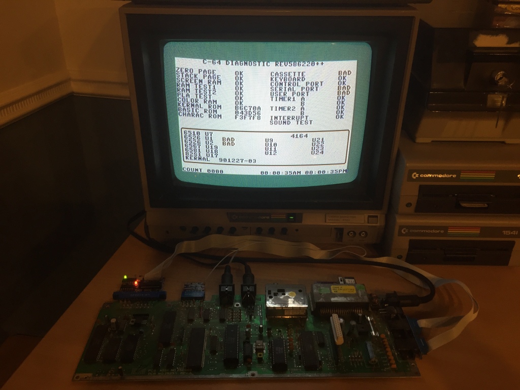
I removed both 6526 CIA ICs (U1 and U2) using my desoldering station (a Duratool D00672) and tested them in my C64C test board, and (surprisingly) both seemed to be working fine. I installed a set of sockets (allowing the quick removal of ICs without the need for rework) and refitted the original ICs.
Alongside the 6526 CIAs being at fault, as these are responsible for controlling the faulty interfaces, there is also the Schmitt-trigger inverter (74LS14) which handles receiving bus signals, and the output driver (7406) which handles transmitting bus signals.
I connected up a known-good 1541 disk drive, and it would reset when the board was powered on, meaning that the serial reset signal was being generated correctly.

This signal, along with all the other serial output lines, is buffered by the 7406 inverter at U22, indicating that this was a potential failure point.
I removed U22 (7406) and tested it using my MiniPro TL866II – it tested fine, so I installed a socket and reinstalled the original IC.
At this point, I began to suspect a problem with the serial port protection circuit, as it was in the ASSY 250469 board #1.
On most Commodore 64 boards, the serial port has a set of diodes between each output line and both the supply rail and ground, to try and limit damage when in case the port is plugged in incorrectly. If any of these diodes have failed, this can prevent the computer from transmitting correctly over the serial port.
I checked the diodes in question (CR9 and CR11-CR17, all 1N4148) in-circuit using the diode test function of my multimeter, and several of them were measuring inconsistently. The full set had obviously experienced a lot of stress, so I decided to replace the whole lot – they’re not an expensive part. I used an equivalent diode, the 1N914.
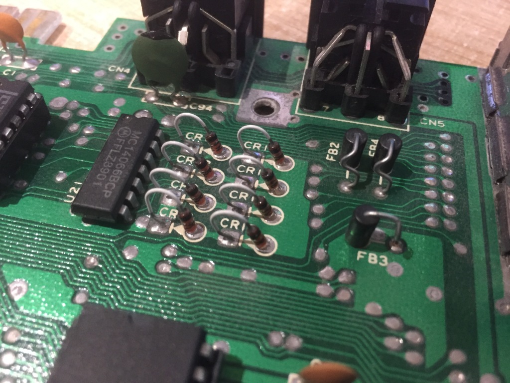
After this, the board then passed all tests with a diagnostic cartridge and loopback harness installed, including all the tests that had failed previously.
Fully tested with diagnostic harness; composite video output OK; luma/chroma video output OK; audio output OK; cleaned ports, power switch, and edge connectors.
Commodore 64 250469 Board #8
The eighth board booted OK (with flashing cursor and correct amount of RAM showing).
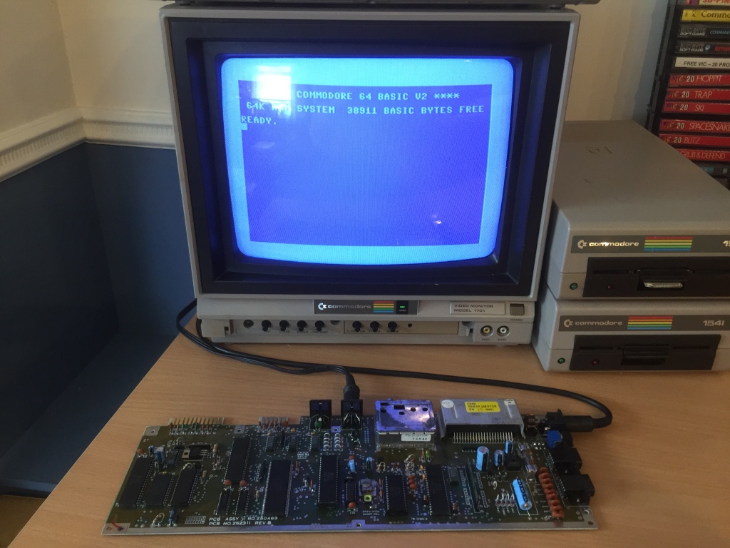
At first things looked promising, as all diagnostic tests initially passed with a diagnostic cartridge and loopback harness installed.
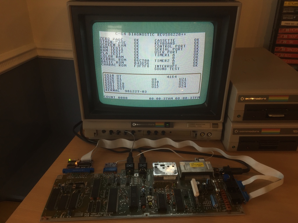
However, after a short while of being turned on, the board started to do funny things: during the diagnostic tests it would either crash to a black screen, crash to a green border screen, or complete the test run without displaying a result for the colour RAM test and indicating several RAM ICs as being at fault (U12, U21-U24).
The indicated RAM failures (U12 and U21-24 in the early board, U10 and U11 in the short board) were likely a red herring, being caused by issues with their associated data lines – after all, the system RAM tests passed OK.
I tried the machine using a dead-test cartridge, which can indicate potential hardware issues (i.e. bad ROM, bad RAM) – the system would crash after failing the colour RAM test, indicating a problem with the DRAM IC at U9 (another red herring).
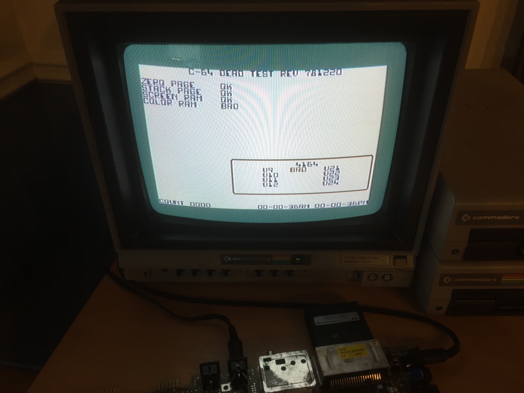
On this version of the ASSY 250469 board (REV B), the colour RAM is integrated into the 64-pin SuperPLA IC (U8) – on the earlier version of the board (REV A), the colour RAM is its own IC (a 2114 SRAM IC at U19).
Based on my experience and that of the community, the 64-pin SuperPLA is a very uncommon failure point, so I decided to leave it for now.
I had an ASSY 250466 board which crashed to the same green-border screen as this one during “RAM TEST 2”, and that turned out to be a bank switching problem with its MOS 6510 CPU – I therefore decided to suspect the CPU on this board, which is usually a MOS 8500 on ASSY 250469 boards, a more modern drop-in equivalent for the MOS 6510.
I removed the MOS 8500 CPU (U6) using my desoldering station (a Duratool D00672) and tested it in my C64C test board, and it was OK, so I installed a socket (allowing the quick removal of ICs without the need for rework) and refitted the original IC.
I did the same for both 41464 DRAM ICs (U10 and U11) in case these were causing problems, but both were OK; at this point I started clutching at straws and did the same for both 6526 CIAs (U1 and U2) and both ROMs (U4 and U5), but these were all OK too.
I had been putting off testing the most problematic IC on the board, the 64-pin SuperPLA – this is very difficult to remove as it is very large, the vias are very small, the pins are very close together, and it has a lot of ground plane connections.
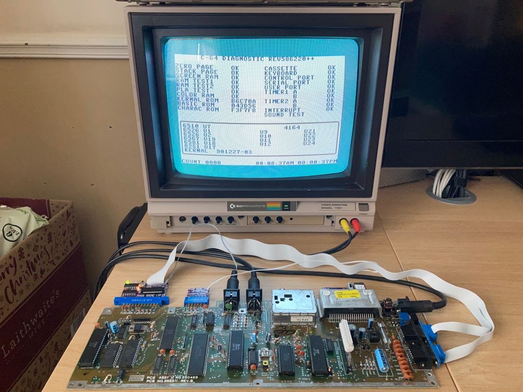
I removed the PLA carefully, installed a suitable socket, and fitted a known-good IC of the correct type (the MOS/SHARP 252535-01, which (unlike the earlier 251715-01) has integrated colour RAM) – the board now seemed to pass all tests with the diagnostic cartridge and loopback harness installed, and worked fine for prolonged periods.
Fully tested with diagnostic harness; composite video output OK; luma/chroma video output OK; audio output OK; cleaned ports, power switch, and edge connectors.






Love your Blog!
LikeLiked by 1 person
Thank you 😊
LikeLike
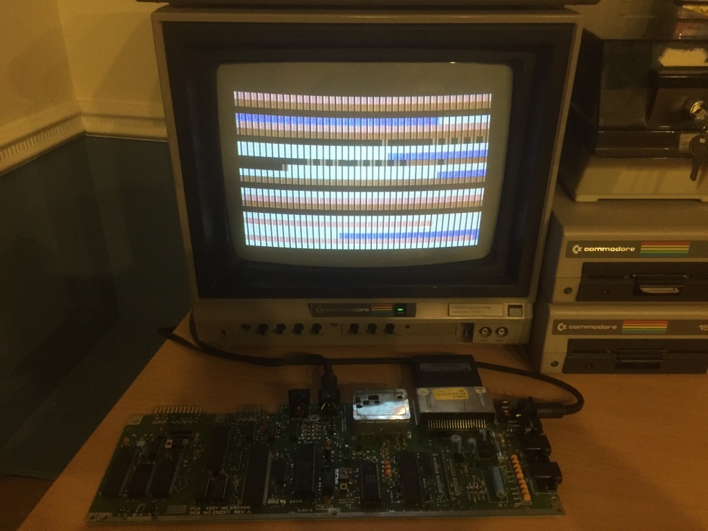
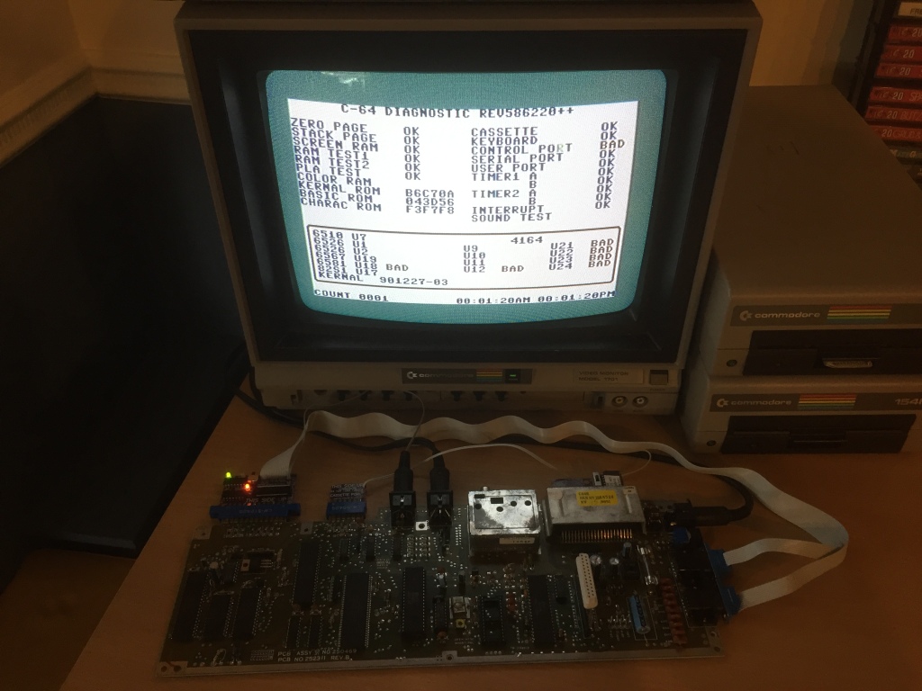
Hi there, I love your website and find it very helpful. Thank you for doing it. I have some problems with this board, and due to limited resources and knowledge struggle a bit finding what is wrong with it. Symptoms are as follows: the C64 always boots to a black screen. I have a dead test/diag cart but no harness. When I put the diag cart in and power it up, it still boots to a black screen. ..but, surprisingly, after I press reset button on the cart, it boots and runs the test. The same is happening when I plug in any other cartridge – first black screen, then after reset it boots. But it still will not work correctly – will not load anything, crashes etc. I have BADs on U1, U2, U18 and on interrupt, and obviously I have no harness, so I have BADs on all ports. The dead test is the only thing that starts without pressing reset on the cart, it runs and completes the test without errors. Upon touching the ICs, I noticed the SuperPLA stays cold, while other ICs get warm (but none gets hot). One other thing is, both tests show the screen a bit like every other vertical line. I just wonder if you came across anything like that before and maybe you will know what the possible culprit can be.
Many thanks. Remi
LikeLiked by 1 person
Thanks Remi, I’m glad you like it 😊 Sorry to hear about your issues. The first step in any diagnosis is to check the power rails on the user port (should be 5Vdc and 9Vac) and reset line on the user port (should be low when the computer is first turned on, then go high after about half a second). It sounds like your board has problems with the reset circuit, perhaps the 7406 logic IC at U22 and/or associated passives. This chip is also used to buffer chip selects and the signals on the serial port, so can cause all kinds of problems. My advice would be to test for the power-on reset pulse and go from there 😊
LikeLike
Hi,
thank you for your reply and your advice, all much appreciated.
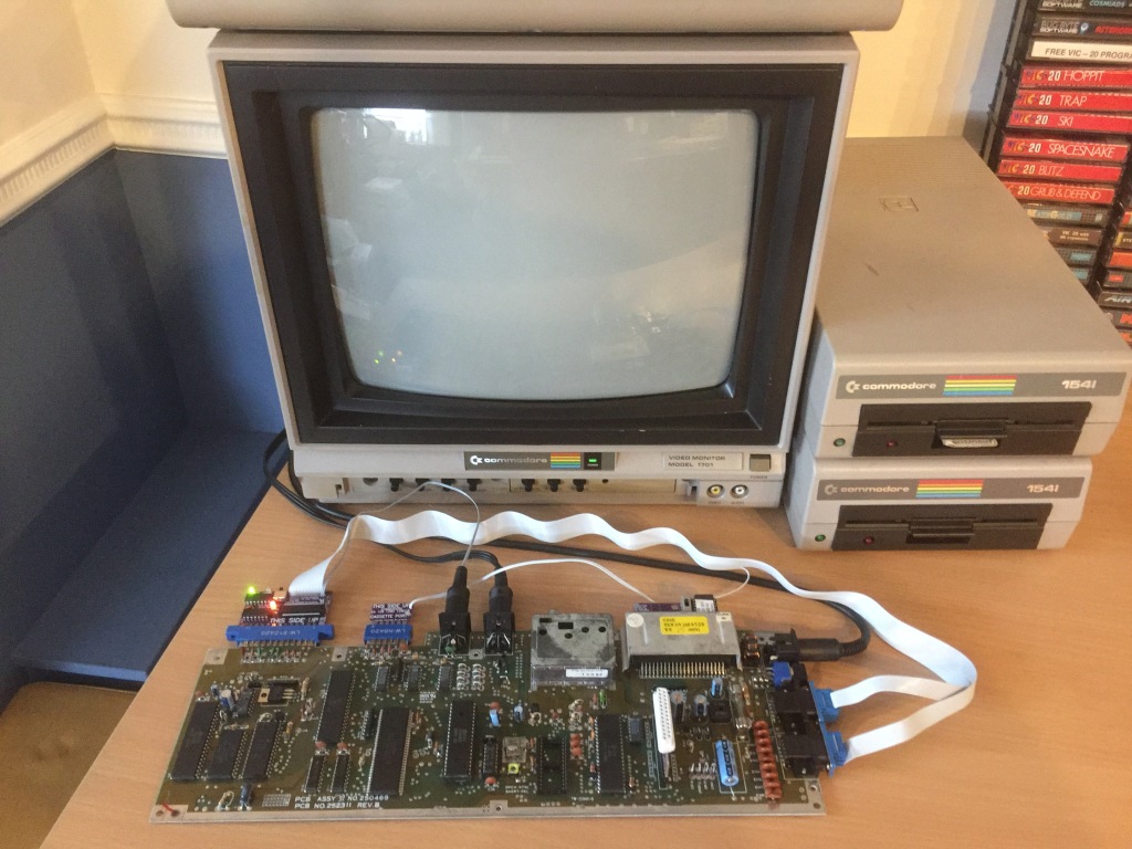
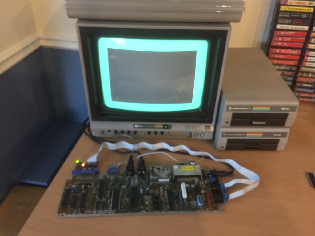
I thought it might be the 7406’s fault. I now replaced it and the computer boots without resetting. But what it displays is still not right – see pictures:
https://photos.google.com/photo/AF1QipOlb_FLpgJ846xKu6m3DgrAcD643dH_QjCSftdL
https://photos.google.com/photo/AF1QipPgaOZUlRKXfzaspTR7lHIMn3aW4KnfPYmp5c45
https://photos.google.com/photo/AF1QipPeYihXwHWuHEqa9nL_ppzEJzgQrvC9QhOwkBxj
First picture is without cartridge, second is ActionPlus and third – the only case where I get a normally looking screen – BlackBox v.3. So the BB cart bypasses something that is not working properly. I checked the VIC II in another machine, and it works fine. The picture is stable and clean from garbage etc. Remaining chips are soldered, so swapping them will be a bit laborious, I do not really know what to check next. Would you have any idea?
Regards
Remi
LikeLiked by 1 person
Hi Remi,
No problem, I’m glad you’re making progress 😊 It’s difficult to see what’s wrong in the photos, is it the zig-zag pattern on the first two photos? I haven’t seen anything like that before, I’m afraid. Is there anything that looks like it on the C64 Pictorial Fault Guide? https://www.pictorial64.com/index.htm#ram
LikeLike
Adam,
apologies, I just realised the links do not work, correct ones below:
And thank you for taking time to reply to my first post.
Regards
LikeLiked by 1 person
Hi Adam,
yes, it was the zig-zag pattern, and no colours. In the mean time, I asked Lemon64.com community for help, and one of the guys there suggested what can be wrong.
Just in case someone has similar problem, the guy’s suggestions were: “Assuming you don’t try to run a PAL C64 on an NTSC monitor (or vice versa), it seems as if the chroma carrier frequency is missing or way off. Have you tried adjusting trim pot CT1 already? If this doesn’t change anything, my guess would be a bad U20 (MOS8701) then.”.
Both of my devices were PAL and I knew MOS8701 was fine because I checked it on another machine. I literally touched the CT1 and screen went back to normal. Simple as that 🙂
Thank you for your input and help.
Regards
Remi
LikeLiked by 1 person
Hi Remi,
That’s great news, nice work 😊
Many thanks,
Adam
LikeLike