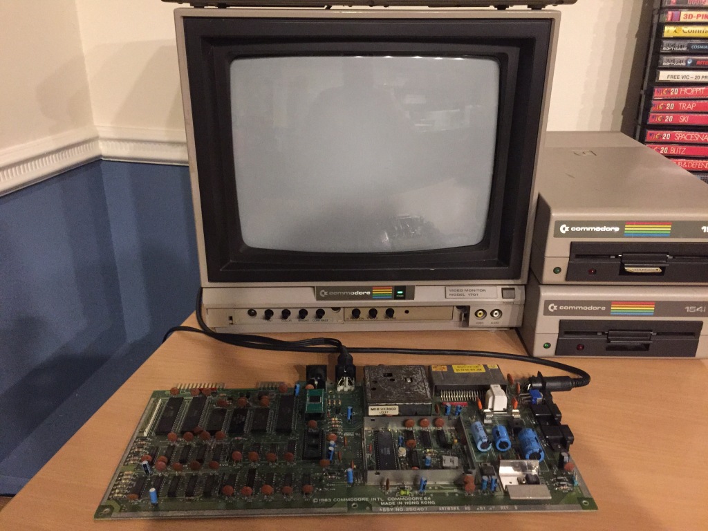
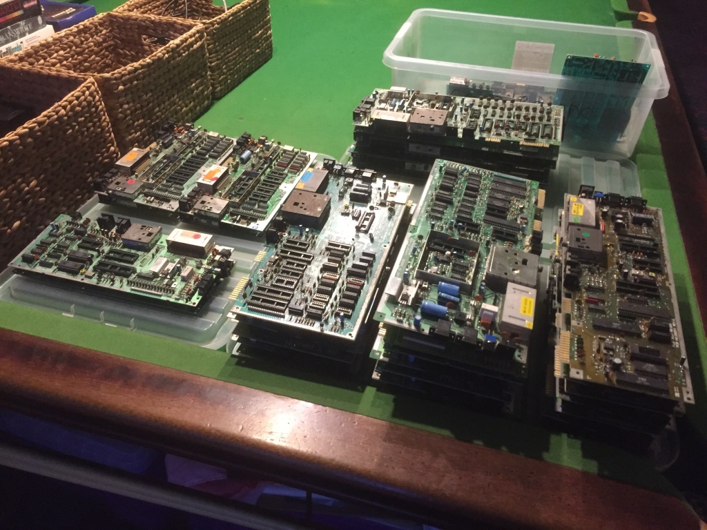
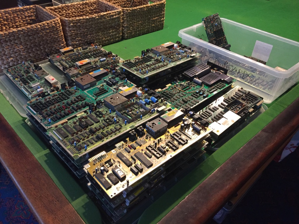
Alongside purchasing complete systems, over the past few years I’ve also accumulated a large quantity of incomplete circuit boards for “spares and repairs”, primarily from Commodore computers (VIC-20, VIC-20CR, C64, C64C, C16, Plus/4, C128, etc).
I got these for cheap in various job lots, with the intention of fixing up as many as possible and selling the working ones on for those who needed a fully-tested board (for swapping into a system, for use as a test board, etc). This meant I could focus on my favourite part of my work – the electronics restoration – without having to worry about case and keyboard cleaning, which is fun but can get quite tedious; also, a reliable supply of original spare parts from irreparable boards.
I recently finished my restoration of the salvageable boards, which has taken a VERY long time (bit by bit for the past year or so) because of both the quantity of the boards and the amount of work involved in testing, repairing, and cleaning each one.
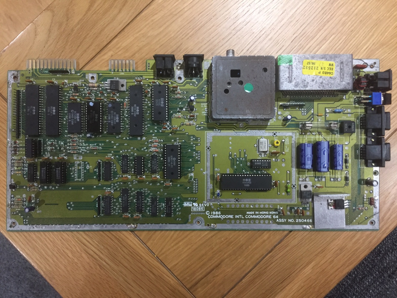
This article focuses on a set of C64 boards I worked on, specifically a large number of ASSY 250466 boards – a rare late revision longboard which followed the ASSY 250425.
Commodore 64 250466 Board #1
The first board needed a lot of work before it could even be powered on: it was missing its fuse, the crystal oscillator and PAL/NTSC wire jumper by the VIC-II, both socketed 41464 DRAM ICs, and two socketed glue logic ICs: the 7406 at U8, and the 74LS08 at U27. The only other socketed ICs were the SID (U18), PLA (U17), VIC-II (U19), and MOS 8701 clock generator IC (U31).
Unlike the earlier Commodore 64 boards which all used eight 64K-by-1bit 4164 DRAM ICs, the ASSY 250466 uses two 64K-by-4bit 41464 DRAM ICs as a cost-saving measure – this was carried over to the later ASSY 250469 shortboards used in the C64C.
I installed a fuse of the correct type, a spare oscillator, a spare wire jumper, a new-old-stock 7406 IC and 74LS08 IC (both available to buy from Retroleum), and two new-old-stock 41464 DRAM ICs (available to buy from Retroleum). I also cleaned the board up and straightened any pins that had been bent in storage by the previous owner, including the power LED and keyboard headers.
I then tested the board with a set of test chips installed, but it would output video but would not boot up correctly, displaying only a blank black screen with no border or text.

In the C64, a black screen fault is a common failure mode which can indicate all kinds of problems: typically, a missing or improper signal, a data or address bus conflict, an addressing problem, or a stack page fault, all of which can be caused by a power issue or a failed IC. Most of the ICs on the board are connected to the data or address bus, so there are a large number of potential problems that need to be worked through.
The first thing to check with any repair is that power is being correctly received on the board, which may indicate a problem with the power socket, power switch, or fuse – I checked for 9Vac and 5Vdc at the user port, and both were OK; I also checked the 5Vdc and 12Vdc supply to the VIC-II, and both were OK.
A constant reset can also cause a black screen – I checked the reset signal at the user port and it worked as expected, staying low (around 0Vdc) for about a second at power on, then going high (around 5Vdc).
I checked for physical damage on the board which could be causing connection problems, including scratches or cold solder joints, but everything seemed OK.
I checked for signs of previous rework which could indicate a potential problem (flux residue, non-factory sockets, etc) – the board had obviously seen a lot of rework in the past for whatever reason, given that both 41464 RAM ICs (U10 and U11) and two logic ICs (U8 and U27) were socketed and wouldn’t have been from the factory. I checked over the installation of all the non-standard sockets (checking continuity on all connections against the schematic, using my multimeter), and everything was OK.
I reseated all of the socketed ICs and cleaned all sockets, ports, and switches with contact cleaner, however there was still no change in symptoms.
I tried the machine using a dead-test cartridge, which can indicate potential hardware issues (i.e. bad ROM, bad RAM) – however, there was no change in symptoms. I tried the same with a diagnostic cartridge, with the same result.
At this point, I decided to aim my investigation at the ICs themselves.
I started by using my IR thermometer to measure the temperature of all of the soldered ICs, to check for any outliers. IC failures often lead to gates shorting or pulling on inputs or outputs, which draws more current, which increases die and package temperature – this can range from a subtle difference to something that could quickly burn your finger (i.e. RAM ICs damaged by overvoltage).
The Kernal ROM (U4, MOS 901227-03) – which is particularly unreliable due to its manufacturing process and because it normally runs hot – was running especially hot (approx. 50°C) even after a short time, so made it suspect. I therefore removed it using my desoldering station (a Duratool D00672), and installed a socket.
I always use high-quality double-sided sockets, which are more reliable than cheap single-sided sockets as they contact the IC legs on both sides – a lot of people push the use of turned-pin sockets, but I don’t like using them as they make swapping ICs difficult, they are difficult to desolder, and they are visibly obviously non-standard.
I tested the original Kernal ROM in my C64 test board, and it also caused a black screen fault in the test board, so it had indeed failed. With a known-good spare IC installed (which are also available to buy from Retroleum), the board now seemed to boot correctly (with flashing cursor and correct amount of RAM showing).

It also passed all tests with a diagnostic cartridge and loopback harness installed.
Now that the board was working again, I wanted to perform some preventative maintenance, starting with the electrolytic capacitors – these are commonly used for filtering, smoothing, and decoupling in both high- and low-voltage electronics.
Electrolytic capacitors typically comprise aluminium windings insulated by a liquid electrolyte, which can dry out over time and negatively affect performance (even failing dead short), or leak out and cause corrosion to the PCB and surrounding components.
As such, I often replace all the original electrolytic capacitors with high-quality modern equivalents – this takes a little while on the C64 longboards, especially the earlier ones, as there are quite a few capacitors which can be tricky to remove due to large ground planes.
I usually remove all of the capacitors at once using my desoldering station (a Duratool D00672), then install the new ones one-by-one whilst taking particular care to ensure that the value, voltage rating, and orientation are correct – electrolytic capacitors are polarised, so must be installed the correct way around, else they’ll blow up during use.
You can’t always trust the markings on the PCB silkscreen, as sometimes mistakes were made in the design from the factory (take the Commodore CD32, for example), so care must be taken to match the orientation of the new capacitor with the original.
I used a commercially available capacitor pack from Retroleum.
Fully tested with diagnostic harness; composite video output OK; luma/chroma video output OK; audio output OK; cleaned ports, power switch, and edge connectors.
Commodore 64 250466 Board #2
The first board needed a lot of work before it could even be powered on: it was missing its fuse, its power socket, its power switch, and the PAL/NTSC wire jumper by the VIC-II; it was also completely missing the Kernal ROM, PLA, and both 41464 DRAM ICs. The only other socketed ICs were the SID (U18), VIC-II (U19), and 8701 (U31).
I installed a fuse of the correct type, a spare power socket, a spare power switch, and a spare wire jumper. I also cleaned the board up and straightened any pins that had been bent in storage by the previous owner, including the power LED and keyboard headers.
I checked over the rework performed by the previous owner – the Kernal ROM and PLA had been removed cleanly, however there was a damaged via on one of the RAM traces. I patched the broken trace with some wrapping wire, then installed sockets on both RAM ICs, the Kernal ROM, and the PLA; I also installed two new-old-stock 41464 DRAM ICs (both available to buy from Retroleum).
I always use high-quality double-sided sockets, which are more reliable than cheap single-sided sockets as they contact the IC legs on both sides – a lot of people push the use of turned-pin sockets, but I don’t like using them as they make swapping ICs difficult, they are difficult to desolder, and they are visibly obviously non-standard.
I checked for physical damage on the board which could cause connection problems, including scratches or cold solder joints, but everything seemed OK; I also cleaned all sockets, ports, and switches with contact cleaner, and edge connectors with an eraser.
I then tested the board with a set of test chips installed, and it seemed to boot correctly (with flashing cursor and correct amount of RAM showing).

I initially ran basic tests on the board using a dead-test cartridge, which can indicate potential hardware issues (i.e. bad ROM, bad RAM), and all of the tests passed OK.
However, when I tried the same with a diagnostic cartridge – which features a more thorough suite of diagnostic tests – the board would crash to a black screen with border on the upper RAM test (“RAM TEST 2”).

This is a failure mode that I hadn’t seen before, and which I suspected was due to either a problem with the RAM itself or the addressing circuitry, which could be caused by a power issue or a failed (or failing) IC. Many ICs on the board are connected to the data or address bus, so there was a large number of potential issues that needed to be worked through.
I double-checked my installation of the RAM and sockets, and even tried another set of known-good RAM ICs just in case, but everything here was OK – the problem was therefore with the addressing side of things.
In its default configuration, the Commodore 64 has 64KB of system RAM, 20KB of system ROM, and 512B of colour RAM – also, either 8KB or 16KB of expansion ROM when a cartridge is installed. However, because the 8-bit MOS 6510 CPU used in the Commodore 64 can only address 216 (65536) memory locations ($0000-$FFFF), the system employs bank switching to “swap” banks of memory in and out of the visibility (and accessibility) of the CPU, allowing it to access all the memory (albeit in a non-contiguous manner).
This is why the initial C64 startup screen only shows 38911 bytes available to BASIC.
Unlike paging, where an operating system continuously moves data between secondary storage (i.e. a HDD) and main memory (RAM or CPU cache), with bank switching the memory state remains unaltered when banks are swapped, and it’s only the accessibility of the memory bank by the CPU that changes. Bank switching is generally not used by modern 32-bit and 64-bit systems due to their large address spaces, but it was a very common practice in 8-bit systems of the 1980s.
In the Commodore 64, bank switching is implemented using a total of five control lines, giving 25 (32) possible memory configurations (modes): three from the CPU (LORAM, HIRAM, CHAREN) for internal memory, and two from the PLA (GAME, EXROM) for external memory.
Only fourteen different modes are actually required, each of which is a combination of various-sized memory banks (all multiples of 4B, or 16 pages). Because these banks are at fixed locations, they can be divided into seven uneven “bank switching zones”.

Anyway, back to the repair: bank switching problems could therefore be caused by both the CPU and the PLA, or their connections. The PLA was a known-good IC, the PLA socket was new, and the PLA connections had been checked. My suspicions therefore turned to the CPU as being the culprit.
I also found another case study on the community-driven “Commodore 64 Pictorial Fault Guide” (which I thoroughly recommend for assisting in fault diagnosis), where someone had found this exact problem, and it had been caused by a faulty CPU.
I removed the CPU (U7) using my desoldering station (a Duratool D00672) and installed a socket. With a spare known-good CPU installed (also available to buy from Retroleum), the board now passed all tests with the diagnostic cartridge and loopback harness installed – no more crashing on “RAM TEST 2”.

Now that the board was working again, I wanted to perform some preventative maintenance, starting with the electrolytic capacitors – these are commonly used for filtering, smoothing, and decoupling in both high- and low-voltage electronics.
Electrolytic capacitors typically comprise aluminium windings insulated by a liquid electrolyte, which can dry out over time and negatively affect performance (even failing dead short), or leak out and cause corrosion to the PCB and surrounding components.
As such, I often replace all the original electrolytic capacitors with high-quality modern equivalents – this takes a little while on the C64 longboards, especially the earlier ones, as there are quite a few capacitors which can be tricky to remove due to large ground planes.

I usually remove all of the capacitors at once using my desoldering station (a Duratool D00672), then install the new ones one-by-one whilst taking particular care to ensure that the value, voltage rating, and orientation are correct – electrolytic capacitors are polarised, so must be installed the correct way around, else they’ll blow up during use.
You can’t always trust the markings on the PCB silkscreen, as sometimes mistakes were made in the design from the factory (take the Commodore CD32, for example), so care must be taken to match the orientation of the new capacitor with the original.
I used a commercially available capacitor pack from Retroleum.
Fully tested with diagnostic harness; composite video output OK; luma/chroma video output OK; audio output OK; cleaned ports, power switch, and edge connectors.


