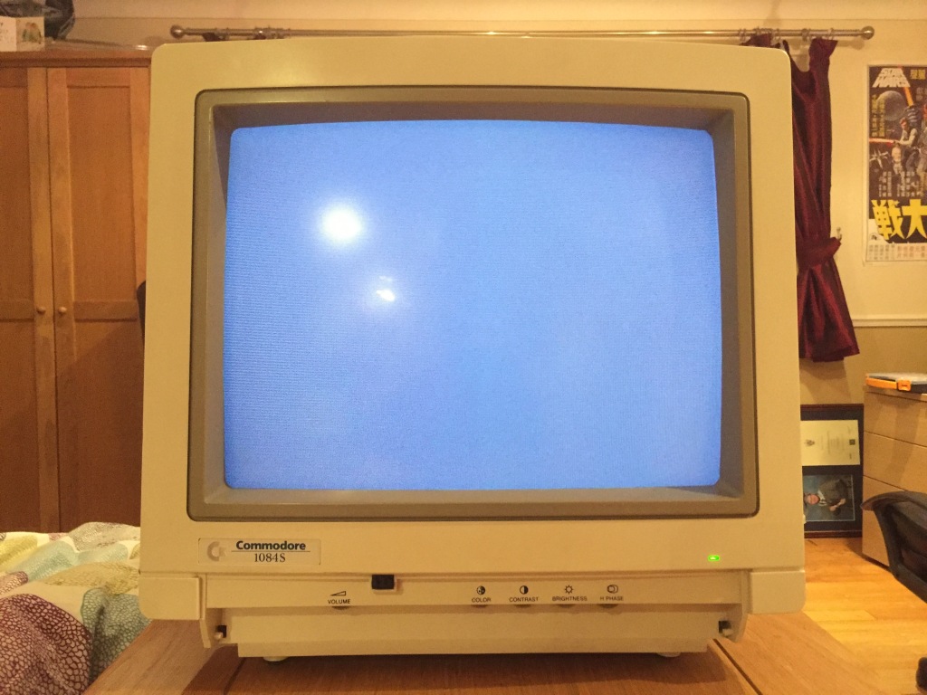
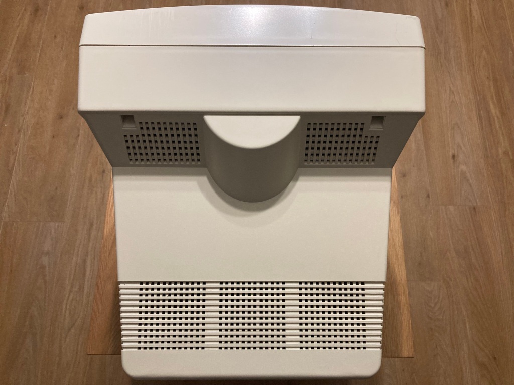
Three years ago, around the time I was first starting to collect vintage computer equipment, I was lucky enough to get my hands on a Commodore C128D 8-bit computer and matching 1084S-D2 CRT monitor.

According to the previous owner, the monitor seemed to work okay except for a broken power switch, which wouldn’t stay engaged – a common 1084 problem.
However, upon arrival the monitor was completely dead – no power LED, no display, no high voltage. Further investigation was therefore required.

The first step was to dismantle the monitor, and inspect everything inside so as to try and locate the source(s) of our problems.
Before we start, a word of warning: like all other mains-voltage electronics, CRTs can be dangerous to work on, so it is important to take care and use the proper precautions – if you don’t know what you’re doing, it’s probably best to leave it to someone who does.
The high voltage side of CRTs can contain extremely high voltages (up to 30 KV), and the “low” voltage side has mains voltage and large line filter capacitors, all of which can give you a nasty shock – most CRTs contain safety features to automatically discharge any stored charge (i.e. bleeder resistors), but even if these exist they can fail, so it’s always best to err on the side of caution.
If you work on a CRT, you do so at your own risk – only work on the CRT when it is powered down, keep one arm behind your back so as to minimise shock across you torso, and ensure that you safely discharge the CRT anode cap before starting work (preferably using a high-impedance lead so as not to damage the CRT coating).

The rear panel held in place with four screws, and simply pulls off; it is connected to the mainboard via a speaker cable, which can be gently pulled from its header.
The neck-board can be pulled (carefully) from the CRT neck; the mainboard is connected to the front panel by several multi-cables and the dag cable, which need to be removed (take lots of pictures to make sure they go back in correctly afterwards); the mainboard is held in place by a set of screws, and can be slid out of its rails once these are removed.


The 1084 series of monitors suffers from poor soldering, particularly on the HV electronics and flyback transformer, so I originally thought that this could be the problem.
However, on opening up the monitor it was immediately apparent the cause – the eagle-eyed amongst you may have already spotted it.

Oh, dear…
The monitor had clearly suffered severe damage during shipping, as there were several large cracks in the PCB originating from one of the screws holding the flyback transformer in place – this was likely due to the lack of support at the centre of the board, coupled with the poor quality of the PCB and weight of the flyback transformer.
I figured that this would be difficult to repair but not impossible, as there was no component damage and the PCB was only single-sided. However, judging by the damage, 53 traces would require repair.

First, I removed the screw onto the flyback transformer as this was preventing the two edges of the cracked PCB from being aligned; then, I carefully flexed the PCB and settled out any overlapping edges; then, I applied epoxy to the outermost crack, clamped both sides together, and left the board to dry overnight.
Then, I carefully removed approximately 4mm of solder mask from each of the affected traces; then, I applied flux and solder to each of the affected traces – I bridged the smaller breaks with solder alone, and the larger breaks with wire-wrapping wire.
While the board was removed, I also replaced the original broken power switch with a new-old-stock part, which was a relatively simple process – the switch itself has four pins, and the metal collar has two pins for extra mechanical support. I first flowed all of these areas with fresh solder (which takes time on the collar, as this draws a lot of heat away from the soldering iron), removed all the solder using my desoldering station (a Duratool D00672), then gently rocked the power switch until it fell out of the board.

After reassembly, the monitor now displayed an image on startup.

I then tested the monitor with the restored C128D, and it seemed to work really well.
- Display works correctly on all video inputs.
- Audio output (stereo) works OK.
- All switches, knobs, and dials work OK.
- Power LED works OK.


A difficult and time-consuming repair, but a resounding success! It goes to show that just about anything can be repaired, and saved from the dump.


Very nice set up!
LikeLiked by 1 person
Thank you 😊
LikeLike
Hi. Are you in the UK? I have a non working 1084st. Would you be able to have a look at it? I’d pay for a repair? Thanks John
LikeLiked by 1 person