
Earlier in 2025, I bought my first IBM PC, a 1983 5160 (XT) with matching monochrome IBM 5151 CRT display and IBM Model F keyboard. I’ve been wanting to get hold of an IBM PC for a while now, as it’s an interesting piece of history, and I’ve enjoyed several videos from Adrian’s Digital Basement on them.
This was a literal barn find, having came from a barn on a farm in York, about an hours’ drive for me – everything was dirty, a bit rusty, and was apparently untested so was being sold-as-seen on Facebook marketplace.


The IBM Personal Computer XT (PC/XT) 5160 is the successor to the original IBM PC 5150, and is very similar except for the addition of three additional ISA 8-bit expansion slots (a total of eight), a base RAM of 128KB expandable up to 640KB, a 10MB MFM hard drive with disk controller, and an upgraded 130W internal power supply. Like its predecessor, the 5160 has a 360K 5.25″ floppy disk drive, IBM BASIC in ROM, and a socket for an Intel 8087 arithmetic coprocessor. By 1985, the IBM PC AT made the XT obsolete for most customers.


I wanted to bring this PC XT back to life, and also make it a lot more usable today – as such, I planned out its restoration into the following main steps, including performing some preventative maintenance before attempting to power it on for the first time:
- Power supply rebuild.
- Mainboard and ISA card servicing.
- Hard drive repair.
- Floppy drive servicing.
- Case disassembly and cleaning.
- Keyboard disassembly and cleaning.
- CF card configuration including DOS installation and HDD backup.
- Modifications including new ISA cards, BIOS update, and co-processor upgrade.
Computer disassembly
The first step was to remove the upper case, which is held in by five slot-head screws, then should slide forwards to the front of the case and pull up and off.


My machine seems to be dated 3rd February 1984.
I then removed the original 5.25″ 10MB HDD, which had been disconnected from power in the past, probably indicating issues with it – so I didn’t have high hopes it would work. This is held in by two slot-head screws on the outer side, one slot-head screw in a pillar accessible underneath the computer, then its power and data cables.


I took this opportunity to remove the ISA cards, which are mounted in a similar manner to modern PCIe cards – they are held in place by a screw and can then be carefully removed from their slot. This computer had the following cards fitted:
- IBM 1816101 8-bit MFM HDD controller card.
- IBM 1501483 8-bit MDA video / parallel card.
- IBM 1501484 8-bit FDD controller card.
- 8-bit PC 512K RAM card v2.0 (FT 850609).
- 8-bit Microsoft InPort device interface card.
- 16-bit generic serial/parallel card.


I then had enough room to remove the PSU, which is held in by four screws along the back of the computer as well as its power cables – it should then slide forward and out.

The 5.25″ FDD can then be removed – it is held in with the same manner as the HDD.

The mainboard can then be removed – this is held in place by to screws and several plastic stand-offs, which can either be removed from the mainboard, or left in place and the mainboard slid out with the stand-offs still attached. The internal POST beeper speaker also needs to be disconnected.

With the case fully stripped down, I decided to tackle the PSU first.
Power supply rebuild
The 5160 has an internal XT-style power supply, which are apparently now becoming unreliable due to their age – they also need to be serviced before powering on, as they contain RIFA-brand metallised-paper mains filter capacitors which like to fail short-circuit and produce volumes of nasty, acrid smoke, so need to be replaced. It also has a rather loud and rattly mains-voltage cooling fan.


This particular PSU is an Astec AA12151, IBM part #1501438 – I decided to gut it and replace its internals with a modern PC PSU, which is covered in detail in another post.


Mainboard & ISA card servicing
After sorting the PSU, I wanted to perform other preventative maintenance on the XT, including replacing all of the tantalum electrolytic capacitors on the mainboard and ISA cards which apparently have a habit of failing short-circuit due to age.


The mainboard is an IBM 150165 “64-256KB system board” with 128KB RAM fitted. First, I gave the it a good clean – then, I replaced all of the tantalum bead capacitors with equivalent modern parts, taking care to ensure that the capacitance, voltage rating, and polarity of the new ones were correct. I also noticed that the variable capacitor at C1 was in poor condition – this is a 5-30 pF trimmer used to adjust the colour burst signal on composite video, so even though I’m not using composite video out of the mainboard, I replaced it with a roughly equivalent modern part.


The ISA cards all had similar tantalum and aluminium electrolytic capacitors for power supply decoupling, so I replaced all of these too, just in case.


Case disassembly and cleaning
I took the opportunity whilst everything was disassembled to thoroughly clean out the case, as it was pretty dirty – I also removed the front panel to clean it out and to repair some damage to one of the plastic standoffs.
I also fitted a new set of rubber feet, as one of the original cork ones was missing.


First power-on
I reassembled the computer for preliminary testing, which is just the opposite of its disassembly – strictly you don’t need to reinstall everything, but I figured I may as well.


I had already tested the PSU without a load and double-checked that the different voltages were wired up correctly, as this could cause major damage if wrong.
Initially, I didn’t have a display to test with as I was still refurbishing my 5151 CRT – I tried turning the machine on, and after a while the onboard speaker beeped with a POST error pattern, which meant that the computer was at least booting up.
I tried again when the MDA display was refurbished, and I got a good image from the computer – it correctly showed 640KB RAM installed but gave POST codes 301 (keyboard), 1701 (HDD), and 601 (FDD), so it wasn’t completely working correctly.

Keyboard disassembly and cleaning
POST code 301 means an issue with the keyboard, typically it not being connected or detected, or it having a stuck key.
The keyboard was filthy, and the “+” key was jammed up because it had been fitted the wrong way around, so I decided to disassemble it for cleaning and see if I could spot any issues with the electronics inside.


It is easy enough to open up, as it is held together with two slot-head screws.


The keyboard had a rather nasty foam dust mat which had badly deteriorated, and was shedding foam everywhere – I pulled all of the keycaps off, removed the metal front-plate (which is held into place with metal tabs and pulls off), then removed the mat.


I then carefully cleaned each key cap, the metal front-plate, the keyboard PCB, and the case exterior and interior.


I then reassembled the keyboard and connected it up for testing – unfortunately I was still getting code 301 despite the “+” key being unstuck. It seems that code 301 indicates that there is no communication with the keyboard, whereas “E0 301” may indicate that communication is OK but there is a stuck key.
I cleaned both the female and male connector with contact cleaner and reseated it a few times while the machine was powered down, and held down “ESC” at power on to reset the keyboard controller, then error 301 went away and I was able to enter BASIC.
I tested all of the keys, and some were not registering properly – these also sounded duller than the other keys, and it appeared that the springs inside the keycaps were not seated correctly – I reseated these, then all the keys worked fine.

Floppy drive servicing
POST code 601 means an issue with the floppy disk controller, either the controller itself or that the FDD is unable to initialise properly.
A common problem with these old Tandon 5.25″ FDDs is that they can get jammed up after long periods of no use, so my first step was to service the drive.


It seemed that the head was completely jammed up, so I managed to carefully free it manually, then cleaned and lubricated the stepper rails. I also cleaned out all of the dust inside the drive chassis, cleaned the home position and disk detect switches with contact cleaner, cleaned the optical write protect sensor, and carefully cleaned both the read/write heads with 99% IPA; I also took this opportunity to replace the tantalum bead capacitors on the drive mainboard, and to clean and exercise the DIP switches on the XT mainboard that select how many FDDs are connected in case these were dirty.


With this work complete, the 601 error went away and I was able to boot to the original test disk which came with the PC documentation packs.


Hard drive repair
POST code 1701 means an issue with the hard drive controller, either the controller itself or that the HDD is unable to initialise properly.
The HDD was connected to power but did not spin up – apparently, MFM HDDs should spin up as soon as power is applied, and do not need a signal from the controller card to do so, so the problem was likely with the HDD itself. If the drive does not get up to speed, then it will not issue a ready signal to the controller card, hence the error.
I dismantled the HDD to see if anything was obviously wrong.


The Seagate ST-412 is fairly easy to disassemble, as per the service manual – the mainboard is held in place with a couple of screws and some delicate ribbon cables.


The drive mainboard was dusty, but nothing was obviously wrong – the drive spindle motor moved freely when the drive was powered down, and when spun manually when the drive was powered up, it didn’t seem to be being magnetically braked (a common issue with these drives is the braking transistors short out and constantly brake the spindle) but is also didn’t try to run at all even with a bump-start. I tested these transistors in case they were shorted, but they seemed OK.


I opened up the drive itself to see if there was any platter damage or if the heads were stuck, and the platters looked perfect – look how beautiful they are! These drives do have an air filter so opening them shouldn’t cause too much of a problem, but be sure to limit the amount of dust that gets into them as much as possible.


I tested the power supplies on the spindle motor drive board as per the service manual and schematic shown below – the +6V supply was missing (sat around 200mVdc), and the 1/2W power resistor R1 (130R) was getting extremely hot (in excess of 100C), which does not seem normal. I tested CR2 (6.2V Zener diode) which regulates the 6V rail, and it seemed to have failed short-circuit, both in-circuit and out-of-circuit – C2 failing short could also look like a CR2 short in-circuit, so testing out-of-circuit too is sensible.

Unfortunately the component identifiers are not marked on the PCB, but it’s pretty easy to identify them from the PCB layout below.

I replaced CR2 with a suitable replacement part (1N4735A) and reassembled the drive for testing – sure enough, the spindle motor now ran correctly when power was applied, and the XT even booted to the C: drive with DOS 2.0 installed!
I ran the HDD for an hour or so to free up the bearings – it started off really loud, then settled to a more healthy consistent noise, albeit still loud!


CF card configuration including DOS installation and HDD backup
I wanted to add some modern storage to the system, to replace the loud and unreliable 5.25″ HDD but still allow me to easily back up and modify its contents via a modern PC. A common way to do this is using an XT-CF card, which uses a flash card with no moving parts, a much better read/write speed, and much lower power consumption.
I bought and built, fitted, and configured an XT-CF Lite v4.1 8-bit ISA card kit coupled with a compatible 64MB CF card – configuration notes are below:
- R5 should not be fitted, as this will cause issues.
- I set the ROM address to D0000 (2.3/5/6/7 on, 2.4 off), above MFM at C8000.
- I enabled the BIOS expansion ROM (2.1 on).
- I enabled write enable for configuration (2.2 on).
- I set the I/O address to 0x300 (1.1/2/3/4 on).

I also upgraded the onboard ROM to use a later version of the XT-IDE Universal BIOS (XUB), specifically v629, by writing the updated ROM image to the AT28C64 EEPROM that came with the kit using my programmer.
I also 3D-printed and attached a mounting bracket for the card – similar brackets are available to buy online if you don’t have access to a 3D printer.


The next step was to prepare the CF card and install DOS. The CF card ideally needs to be prepared with partitions in the PC XT itself as otherwise it probably won’t work correctly, but after this it can be connected to a modern PC via a USB-to-CF adapter and files written, read, and modified easily and reliably.
I didn’t have any 5.25″ DOS install disks, so decided to use 3.5″ disks instead, as I could easily write these from my modern PC using a suitable USB floppy disk drive. This meant installing a 3.5″ FDD into the XT temporarily at A:, using a 5.25″ to 3.5″ data cable adapter.
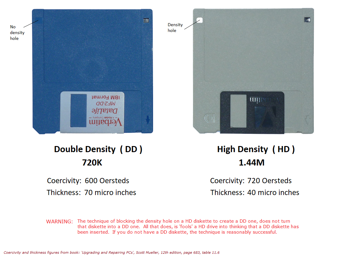
The XT can support 720KB disks with a BIOS update, which I discuss later in this post. I formatted a set of 720KB double-density (DD) disks under Windows 10 using command prompt, then wrote a DOS 3.3 image to one of them using WinImage.


With the original 10MB HDD disconnected, I used FDISK on this boot disk to create two 32MB partitions on the 64MB CF card.


I then formatted these two partitions and installed DOS 3.3 from this same boot disk.


I then temporarily reconnected the original HDD at C:, and made a disk with the XCOPY utility on it to back up the contents of the HDD at C: to one of the CF partitions at D:. Once this was done, I backed up an image of this CF partition using my modern PC, and was able to modify files on both C: and D: of the CF card using my modern PC as required. At this point I also permanently disconnected power to the original HDD and removed the original HDD controller card, as both of these were now redundant.


I also decided to install Microsoft Works 3.0 from 3.5″ floppy disks.


After all this, the computer booted happily into DOS 3.3 from the onboard CF card.

Modifications including new ISA cards, BIOS update, and co-processor upgrade
I wanted to do some other minor tweaks to improve the system overall.
I decided to upgrade the original BIOS ROMs to the latest 5160 BIOS image dated 09/05/1986, using < 250ns 27C256 EPROMs using my eraser and programmer – this BIOS adds 720KB floppy disk support which I needed for using 3.5″ disks to install DOS earlier in this post, but may introduce issues with some third-party floppy controllers.

I bought and fitted an Intel 8087-1 coprocessor to improve maths performance of the system, and set the mainboard DIP switches to enable it as required; I also fitted a pair of self-adhesive heatsinks to the CPU and coprocessor to aid cooling, as the coprocessor in particular runs quite hot.


I bought and fitted an RTC8088 8-bit ISA RTC card to keep the system time when the system is powered down, and avoid having to re-enter the date and time at each boot – this involved fitting a CR2032 battery, adding the necessary driver DSCLOCK.SYS to the root of C:, and adding the line “DEVICE=DSCLOCK.SYS” to CONFIG.SYS.


I bought and fitted an 8-bit ISA serial/parallel card to replace the 16-bit multi-I/O card that was originally fitted, as a lot of the functionality was not available in 8-bit mode.


I bought and fitted a Hercules-compatible MDA card with 720×348 pixel graphics mode in place of the original IBM MDA card, as this supports higher resolution and is significantly smaller in physical size.


I also updated the contents of AUTOEXEC.BAT using EDLIN to load the existing mouse drivers for the Microsoft InPort card, show the installed IBM DOS version, and show the system date and time from the RTC on startup.

Overview & Testing
Once the system was complete, I reassembled everything and it all worked OK.


The refurbished PC XT is shown below alongside my refurbished 5151 CRT display.


This restoration has been a major success – the computer has cleaned up really well, and is now working perfectly with some pretty significant upgrades.


That’s a superb resto bud. It’s great to see this old tech being preserved. Well done, excellent post 👏
Thanks mate, I’m glad you enjoyed it ☺️
It’s very nice to see it all come together. Good work on the hard drive, even though I was a little surprised when you exposed the platters – but your reasoning was sound. I particularly liked the work on the keyboard (I’m one of those people who own too many keyboards).
PS I enjoyed the podcast/broadcast.
Thank you very much mate, I’m very grateful ☺️ Yes, opening the HDD completely like that was quite extreme, at that point I didn’t expect to get it working unfortunately – but thankfully I managed to find the issue eventually!