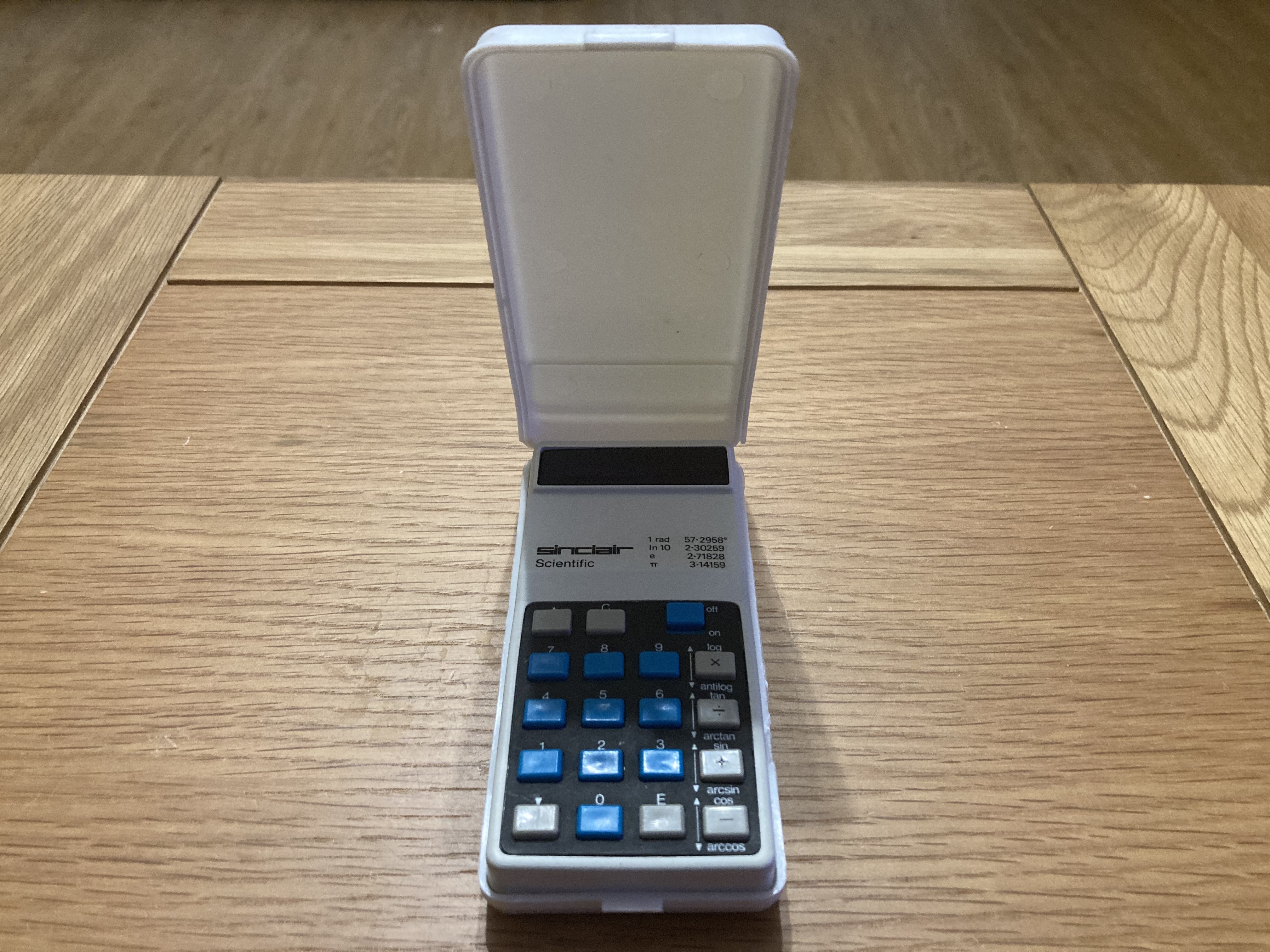
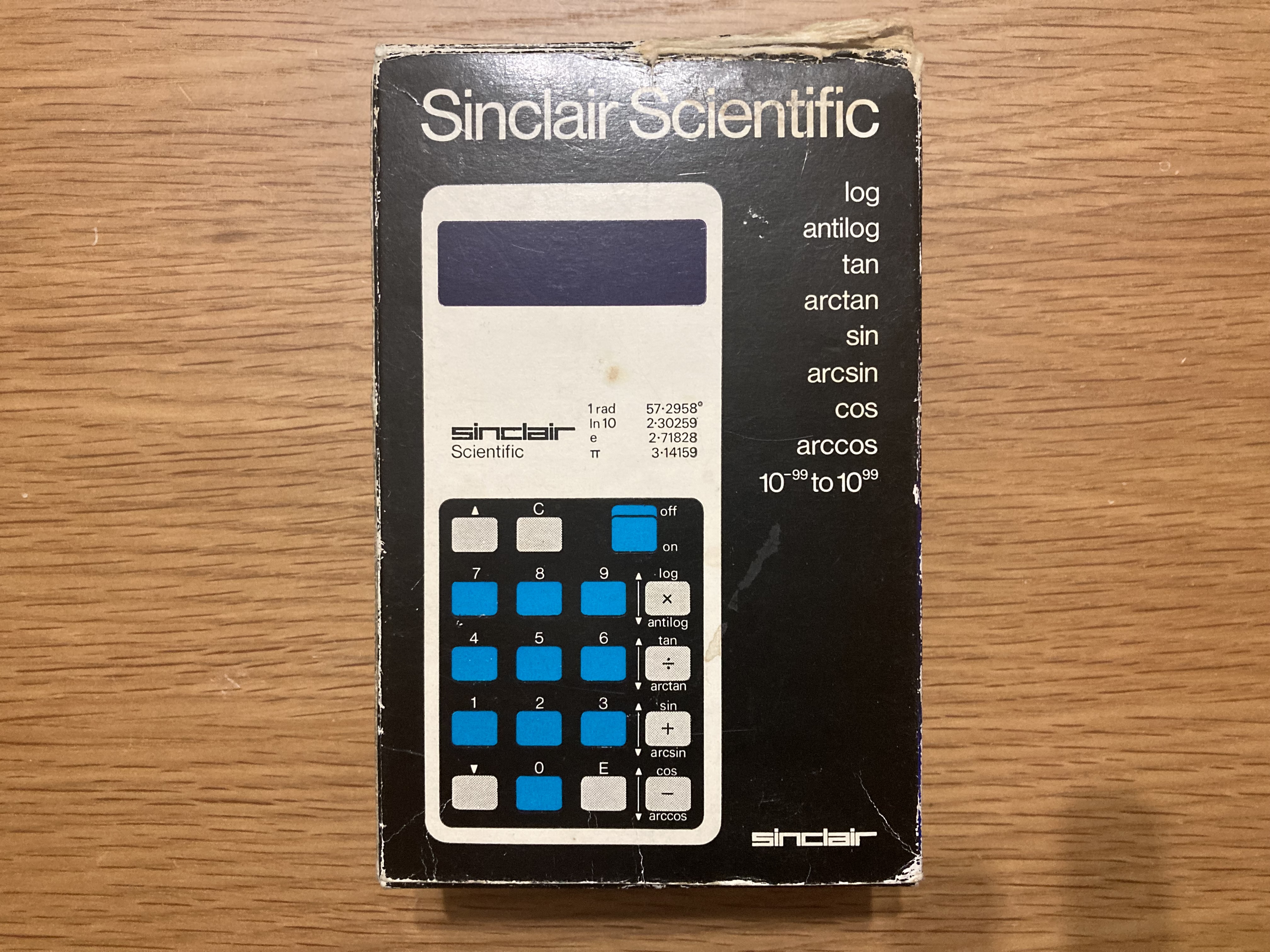
I recently acquired a Sinclair Scientific calculator from 1974, alongside a large bundle of vintage computers – this was an unexpected (but very welcome) surprise and is in fact my first vintage calculator, though it is basically a pocket computer, so it is certainly in keeping with the rest of my collection. The calculator was in good condition and came with its original box, user manual, and carry case, however it was bought sold-as-seen and had several corroded and damaged battery contacts.
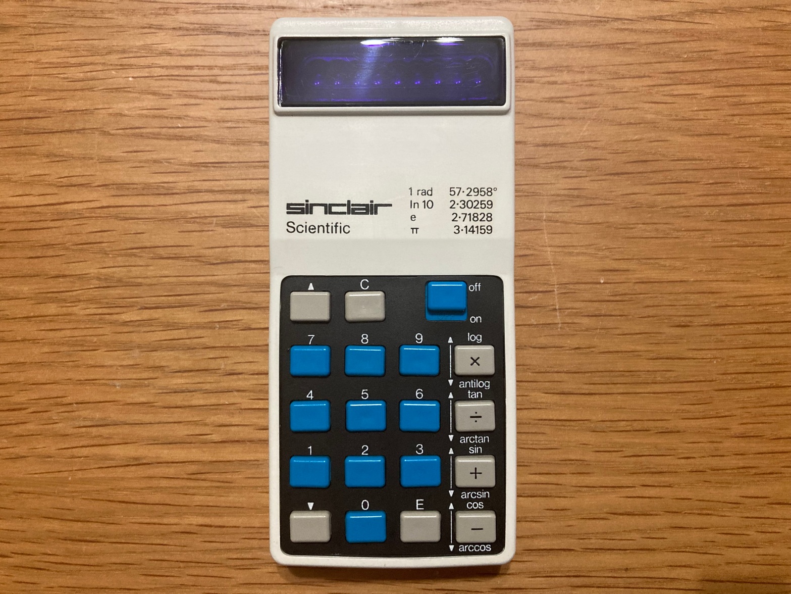
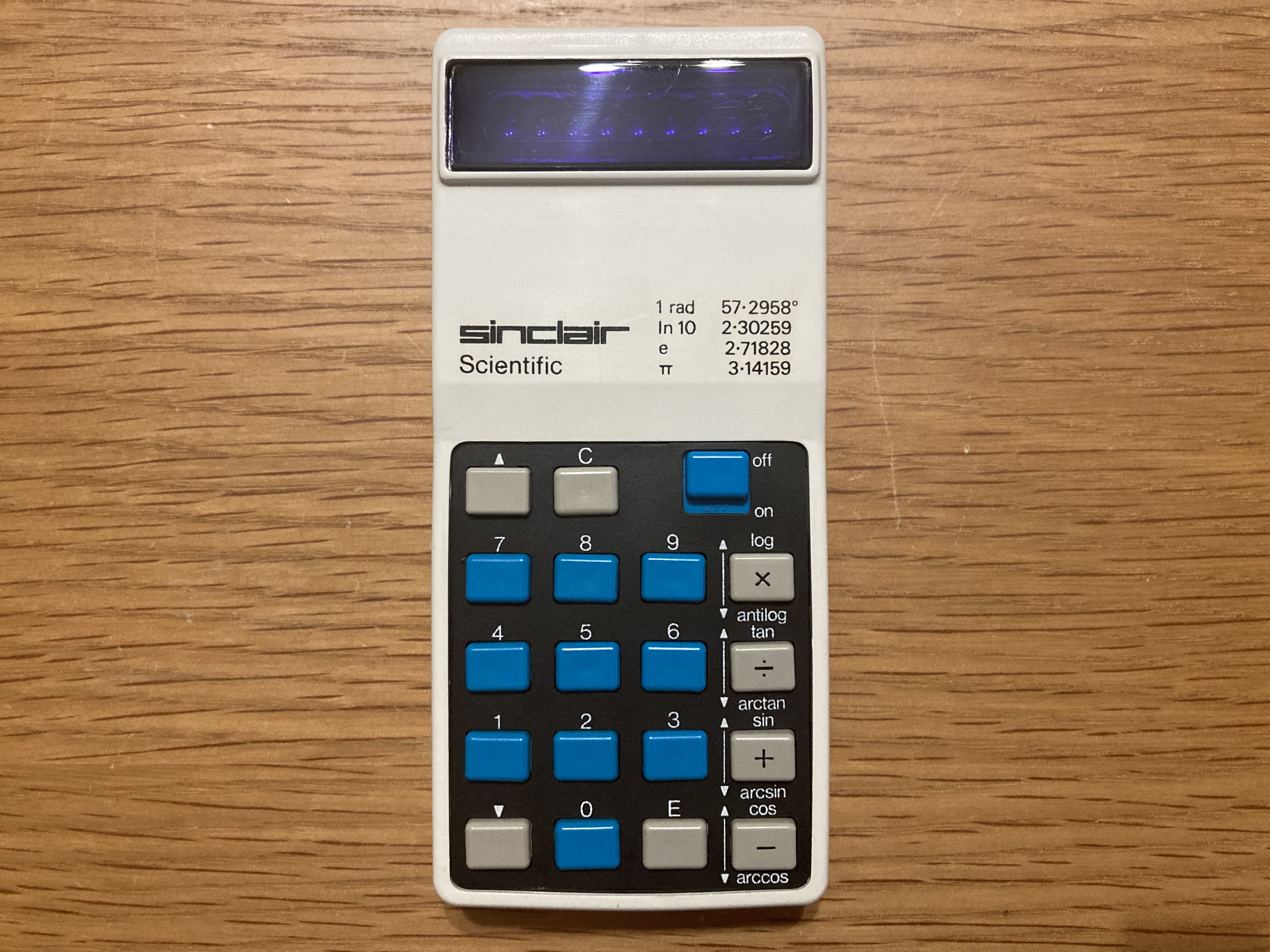
The Sinclair Scientific pocket calculator was released in 1974 by Sinclair Radionics Ltd, following the release of the world’s first handheld scientific calculator, the HP-35, in 1972. It is a 12-function, pocket-sized scientific calculator which initially retailed at £49.95, dramatically undercutting in price other calculators available at the time. It was based around the Texas Instruments TMS0805 IC, which could only store 320 words and was barely capable of four-function arithmetic – however, by sacrificing some speed and accuracy, Sinclair used clever algorithms to implement full scientific instructions. This also increased complexity for the user, for example: constants were printed on the case to be input manually instead of being stored on the calculator, to save storage space; the calculator uses Reverse Polish Notation (RPN) to input calculations, simplifying the hardware design but making it more difficult to use.
The Sinclair Scientific sold in reasonable numbers between 1974 and 1976, when it was discontinued – its competitive pricing and availability in both assembled and kit form made it popular across the entire course of its lifetime.
For anyone who is interested, Ken Shirriff has reverse-engineered the firmware for the Sinclair Scientific, and made an excellent simulator for its algorithms.


The calculator was “sold-as-seen” for spares/repairs – the previous owner had bought it in unknown condition many years ago, and it had damaged battery terminals so could not be easily tested, certainly not using batteries.


Rather than test the calculator first using a benchtop power supply, I opted to attempt to replace the battery contacts first, then test it using batteries.
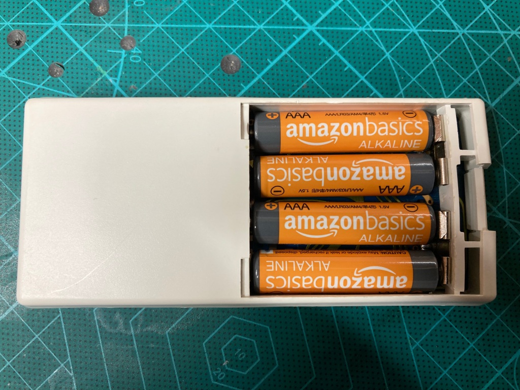
The Scientific uses four standard AAA 1.5V batteries (MN 2400) in series, giving 6V in total. It was difficult to work out the correct orientation for these as this calculator was missing its battery sticker, however I managed to find an image online of one – see below (despite this being a Cambridge, a lot of the design is shared). Somewhat counter-intuitively, the negative connection to the batteries is the switched side.

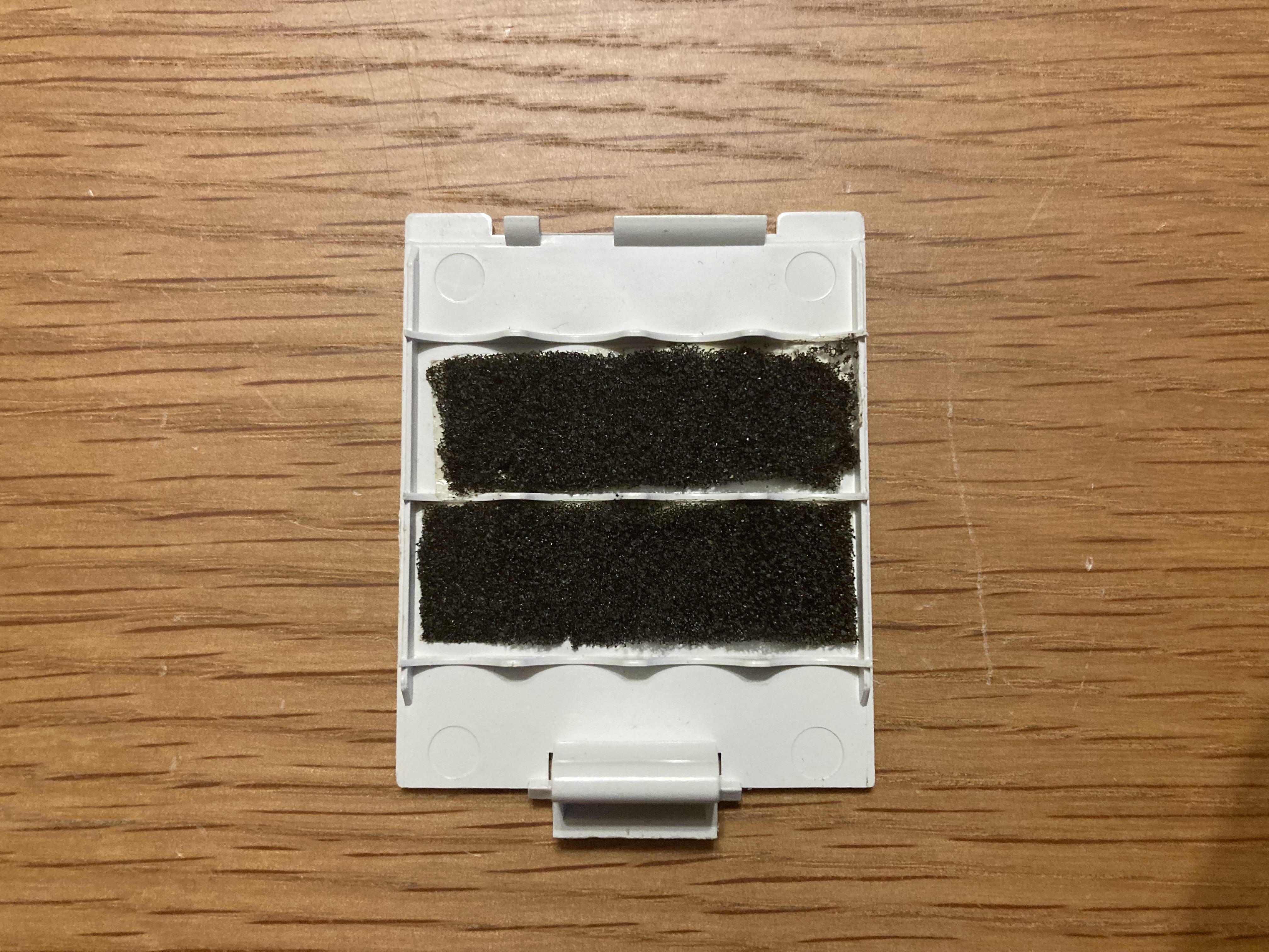
Battery contact wear and failure seems to be a common problem on Sinclair calculators, however I couldn’t find any references to anyone actually repairing or replacing broken contacts. As such, I decided to look for some off-the-shelf battery contacts designed for standard AAA batteries, and try my best to adapt and retrofit them.
The Scientific uses two one-way AAA contacts, and three two-way AAA contacts.

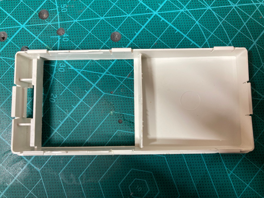
The Scientific is easy enough to disassemble, with several plastic clasps around the edges of the case which can be popped open using a flat instrument – care must be taken to ensure that you don’t damage the case, as the plastic is very soft.
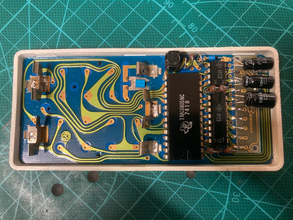
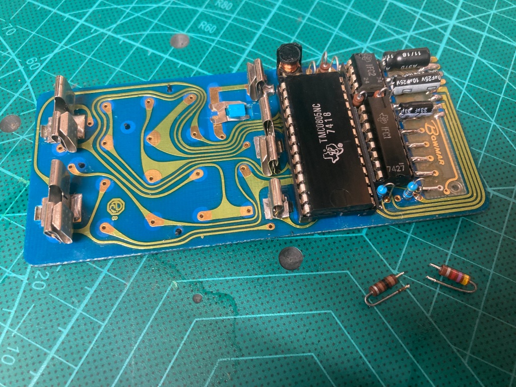
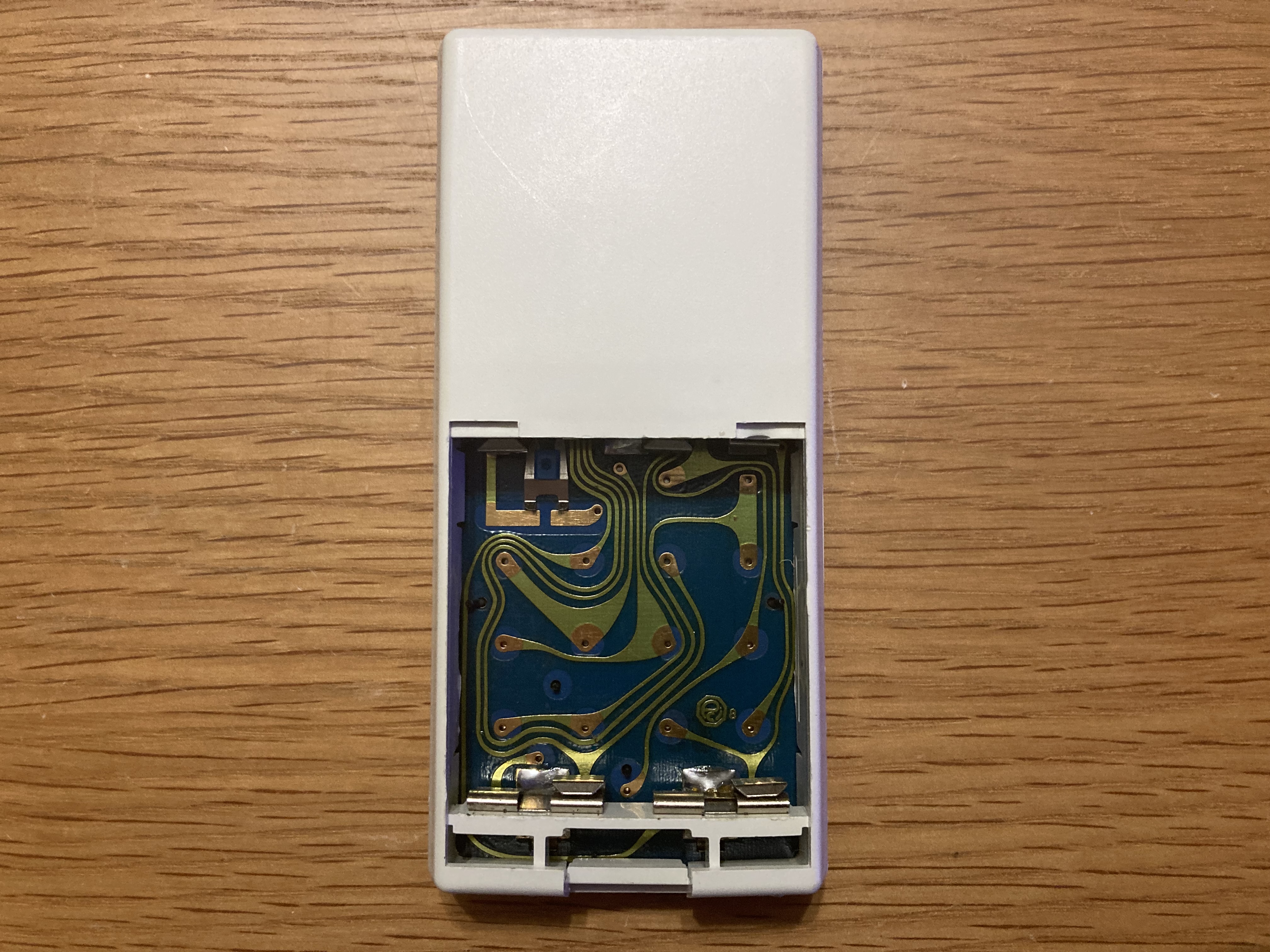
Once the case back is removed, the PCB simply lifts out of the case front. It’s a beautiful design, classic 1970s – a blue board with wavy, hand-drawn traces, green solder mask, and gold plating. It would make a lovely living room wallpaper!
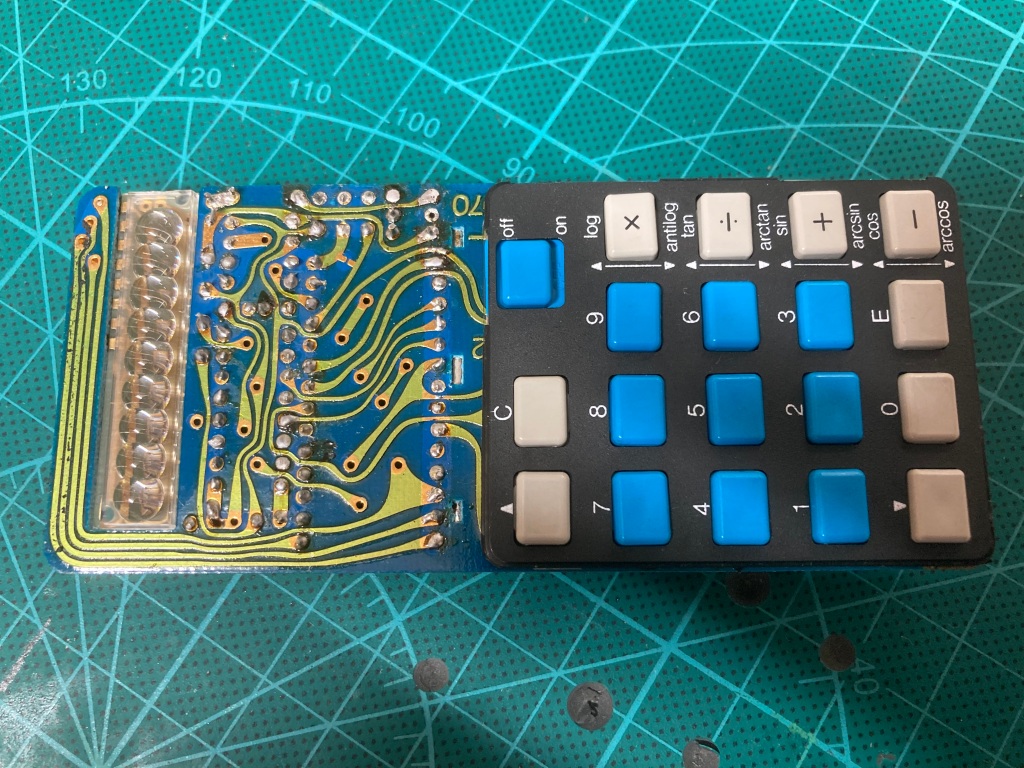
It was quite clear that this must have been a kit-built calculator, given the poor quality of the soldering work, the flux residue, and the lack of battery contact insulation pads and the battery type/orientation sticker.
I installed the replacement battery contacts one by one. The replacement contacts that I had chosen were designed for clipping over plastic cases, instead of surface-mounting like the originals – as such, I simply cut down each original contact using a pair of cutters until it was straight, then slipped the new contact over the original.

I then soldered each replacement contact to the original contact and the pad underneath, making sure to flow enough solder to create a stable joint with the pad.
Great care must be taken to ensure that no shorts are created, either by bridging traces or by shorting the battery contacts out – this is very easy to do as there are several large, bare vias and traces underneath them, so you need to check that there is enough space between each contact and the board below, and adjust the contact accordingly.
The replacement contacts were thicker than the originals, so in order to leave enough space for the batteries themselves, I had to remove the “spring” portion for each of the positive terminals – this was easy enough to do by simply bending and snapping off the spring from the desired terminal on each contact using a pair of needle-nosed pliers.
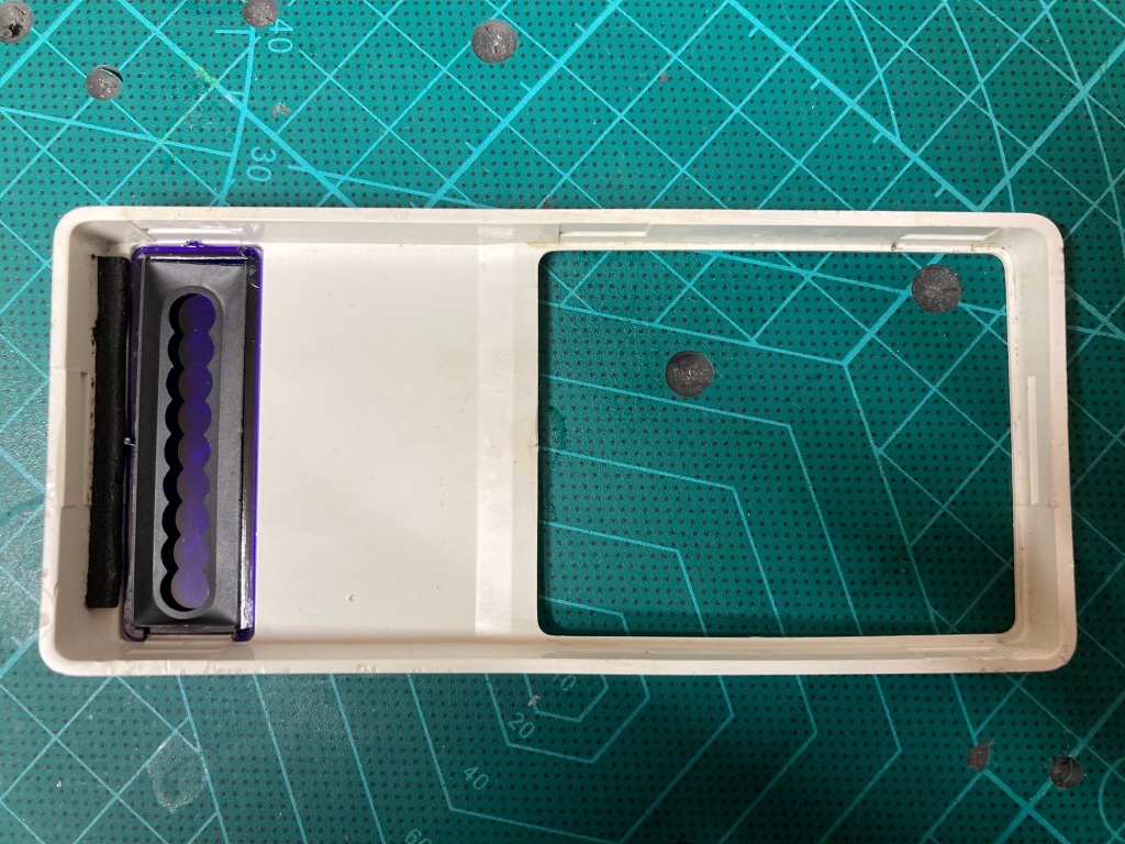
I also had to remove the plastic battery spacer bar from the case, and move the contacts around on the pads until they fit against the inside of the battery compartment on the case – this was easy to modify incrementally by test-fitting the PCB into the case.
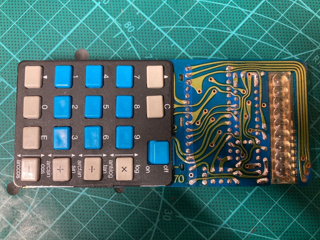
I also cleaned up the PCB, including the button contacts on the underside between the board and the button plate – this plate is held on by several plastic stalks, which in this case were just bent into place, so could easily be bent straight for plate removal.

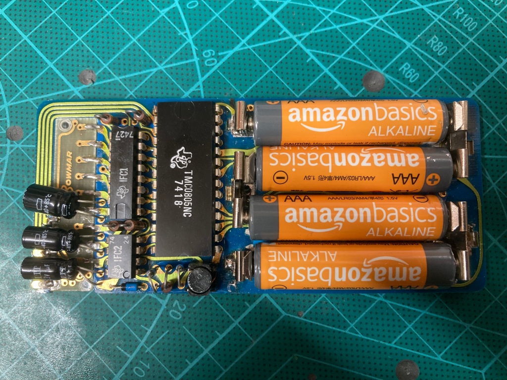
I had to squash down the springs to fit the batteries into position, which was easiest to do whilst the PCB was in the case – after doing so, the batteries fit really nicely.


I tried powering the calculator on, with unfortunate results – the batteries got very hot very quickly (indicative of high current draw, as if something was shorted), so I turned the calculator back off again. During this time, some elements of the display lit up for a short period, then went off completely.
I swapped to using my benchtop power supply, set to 6V with a current limit of 100mA – when turned on, the calculator drew around 55mA which is apparently normal for idle, however it was completely dead (no sign of anything on the display, and no response when any of the buttons were pressed).

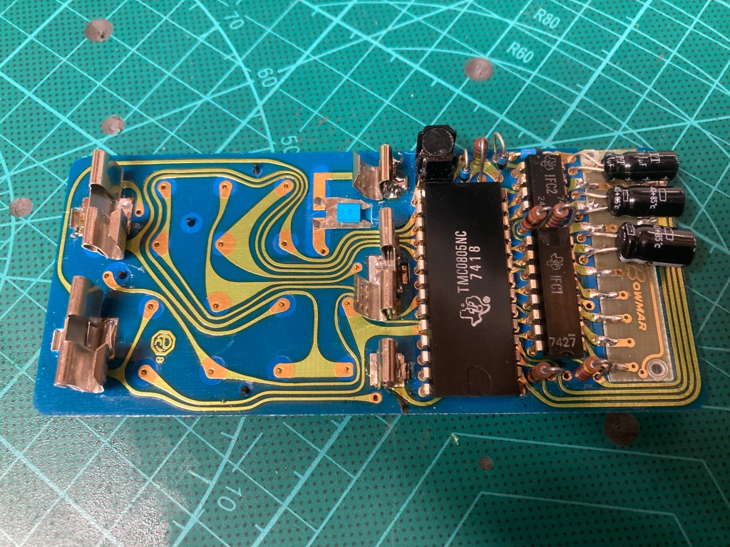
It was therefore time for some troubleshooting – this would be difficult, as I was unfamiliar with the operation and design of the calculator (including its quite complex internal switch-mode power supply circuit), and had a limited amount of spare parts as most of the components in the calculator (bar the passives) are proprietary.
There was also a very limited amount of documentation available for the Sinclair Scientific, however I was able to find a high-quality scan of the assembly instructions, which contained a lot of useful technical information as shown in the following images.

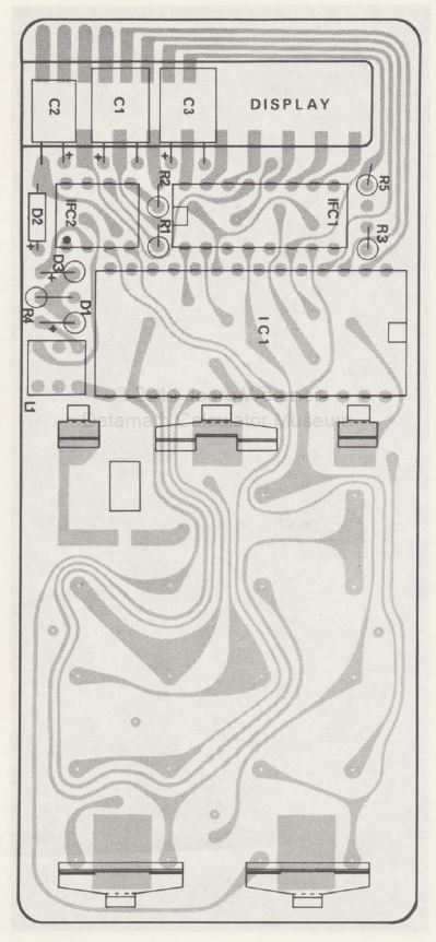
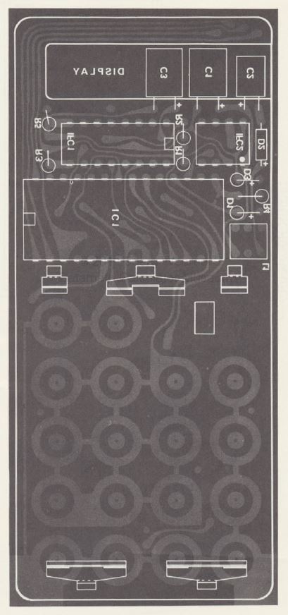


According to the assembly manual, the TMS0803/05 requires a -8Vdc (Vdd) supply rail and a -16Vdc (Vgg) supply rail to operate, which are derived from the +6Vdc battery supply via the internal switch-mode power supply – however Vdd (pin 11 of IC1) measured as only -0.81V, and Vgg (pin 12 of IC1) measured as only -0.01V.
Either the power supply circuit had failed, or a shorted IC was pulling the supply rails down – I decided to remove the three ICs (IC1, IFC1, and IFC2) to check.
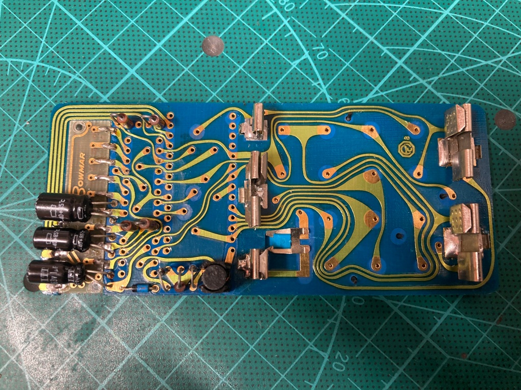
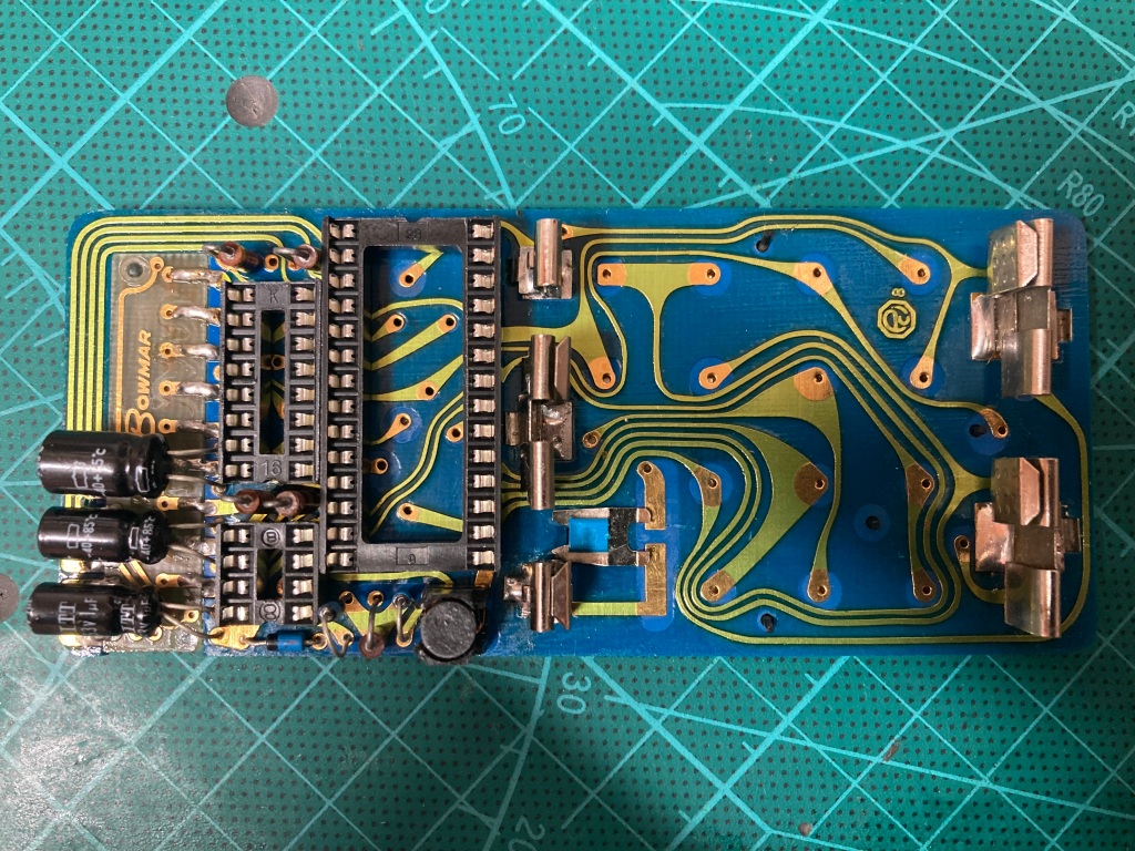
Removing the ICs was relatively easy using my desoldering station (a Duratool D00672) and some rosin flux – the calculator was definitely kit-bought, as the solder quality was very poor (so tricky to work on), and the ICs weren’t even straight against the board.
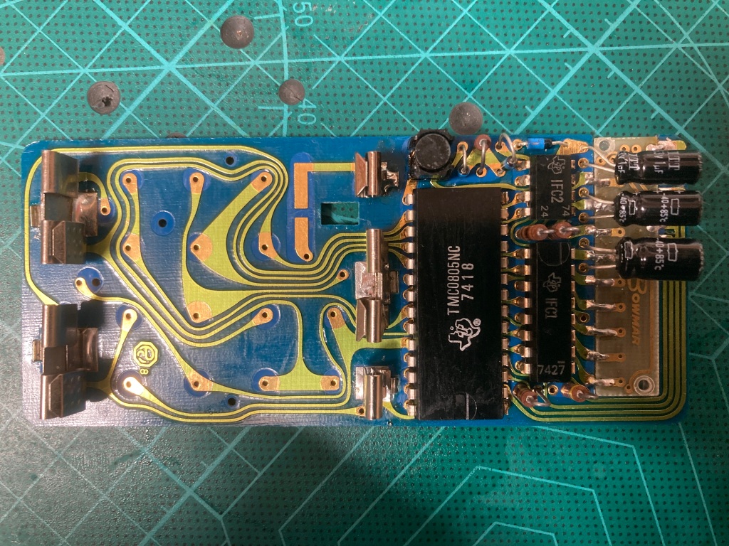
With the three ICs out-of-circuit, the power rails did not change, therefore the power supply circuit itself seemed to be at fault. I installed a set of sockets so that the ICs could easily be removed again without rework.
I always use high-quality double-sided sockets, which are more reliable than cheap single-sided sockets as they contact the IC legs on both sides – a lot of people push the use of turned-pin sockets, but I don’t like using them as they make swapping ICs difficult, they are difficult to desolder, and they are visibly obviously non-standard.
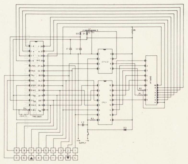
Unlike the TMS0805 which has a fair amount of documentation available online, IFC1 and IFC2 (also produced by Texas Instruments) do not – they are also simply known by this part number, and are proprietary so do not appear to have any equivalent or replacement ICs available. Judging by their placement in the schematic, IFC1 is used to drive the display, whereas IFC2 is used in power regulation.
The internal power supply circuit design is relatively complex, and it appears to use IFC2 as a basic switching regulator. IFC2 itself is powered from the +6Vdc battery input (pin 1 as +6Vdc which is used as the common reference, and pin 2 as 0Vdc); IFC pin 7 is used to drive an AC voltage into the primary side of coil L1 (N:1), using pin 1 (+6Vdc) as a reference; the secondary side of L1 feeds into a full-wave voltage multiplier circuit (comprising D1, C1, D2, and C2), from which the Vdd (-8Vdc) rail (between D1 and C1/R5/D3, which is also used for feedback via IFC2 pin 8) and Vgg (-16Vdc) rail (between D2 and C2) are derived.
Vdd also seems to be used to drive the clock for IC1.

I tested the supply rails again, this time with IFC2 alone re-installed, however this did not seem to make any difference.
Because I had no means of testing the three ICs at this stage, I decided to look elsewhere for the time being, starting with the connections on the mainboard.
Given the poor quality of work performed by whoever assembled the calculator kit in the first place (if you happen to be reading this, sorry!), I decided to redo all of the solder joints on the PCB, and double-check that everything was connected up correctly. I didn’t find any dry solder joints, though I did find one resistor that hadn’t actually been soldered down at one end – if this calculator worked back in the day, it can’t have been too reliable! Unfortunately, correcting this and reflowing and tidying all of the joints did not make a difference to the power supply problem.
At this point, I turned my attention towards the passive components.
I noticed that the 10uF electrolytic capacitor at C1 seemed to be quite swollen, a sign of heavy current handling, as though Vdd had been (or was) shorted out somewhere. I pulled it out the board for testing, and it seemed to test OK – I replaced the three electrolytic capacitors just to be on the safe side, however this made no difference.
I desoldered all three diodes (D1, D2, and D3, all 1N914Es) and tested them out-of-circuit using the diode check function of my multimeter, but they tested fine, so I reinstalled them.
I also desoldered all five resistors (R1-R5) and tested them out-of-circuit using the resistance check function of my multimeter, and two had failed short-circuit: R1 (100ohm) and R5 (4k7ohm). I replaced both of these with modern 0.25W equivalents, however there was still no change in symptoms.
I then desoldered the coil (L1) to check it out-of-circuit – it smelled quite acrid as though it had seen heavy current, and all four contacts had continuity between them (whereas I believe there should be two sets with continuity, the primary and secondary), so I’m pretty sure that the coil was, unfortunately, shorted. I’m unsure as to whether this had been the source of the original failure, however I doubt that – more likely, Vdd shorted out (possibly inside IFC2, where it is regulated) and killed the coil as a result.
Unfortunately, the coil is a proprietary part, and would have been very difficult to repair. Is this the end of our tale? Did I have to call it quits?
Luckily, no! I was so determined to fix the calculator that I decided to take a punt and buy another Sinclair Scientific on eBay – this one was in quite poor physical condition and I didn’t know whether it worked, so I was happy to use it for spare parts.
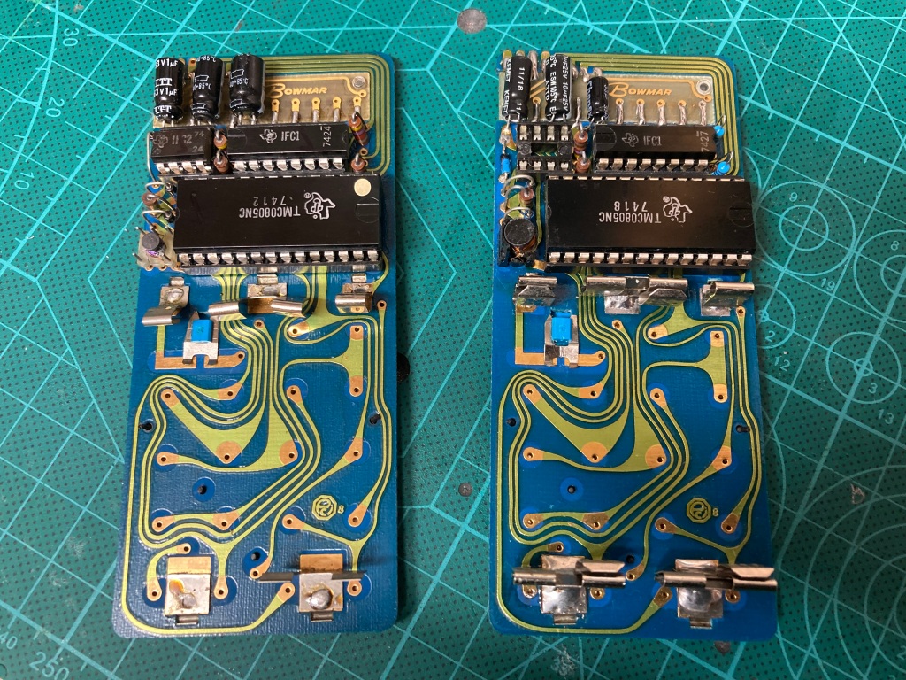
The second calculator also suffered from broken battery contacts – I tried it out using my benchtop power supply, and it worked! This was an excellent starting point for diagnosing the other mainboard.
I decided to desolder and socket the three ICs on the second (known-good) mainboard to allow easy testing of those from the first (failed) mainboard. I then tested the three ICs from the failed mainboard – IC1 (TMS0805) and IFC1 tested OK, however IFC2 had unfortunately failed.
I tested the failed mainboard with the known-good IFC2 IC installed (from the benchtop power supply at 6Vdc with a 100mA current limit set, to avoid potential damage to the IC) and the supply kept going into overload mode, so I shut it off immediately. It appeared that the coil had indeed failed, unfortunately.
Given that one of the irreplaceable ICs from the original board had failed, and that the board itself had a seemingly irreparable fault, I decided to cut my losses on the original board and move the second, known-good mainboard into the good case.
This also meant moving the battery contacts from the bad board to the good one.

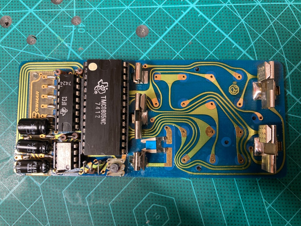


With the new battery contacts installed, I tested the good mainboard and it seemed to work perfectly fine on battery power.
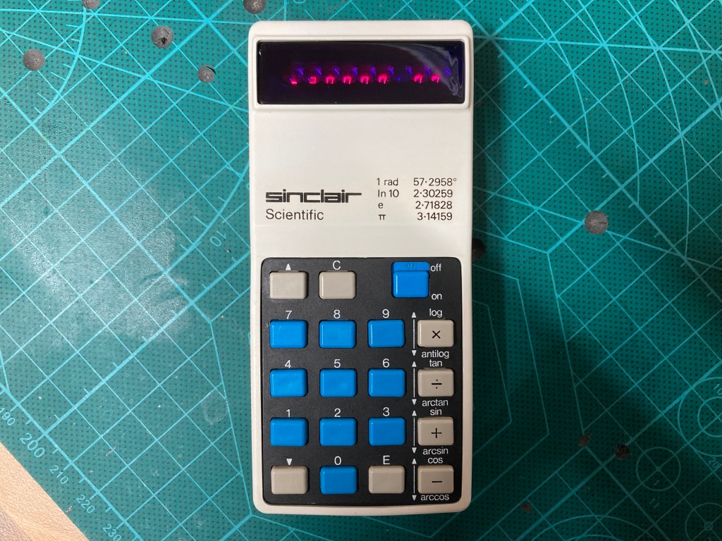
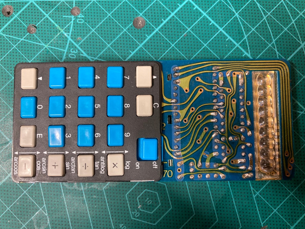
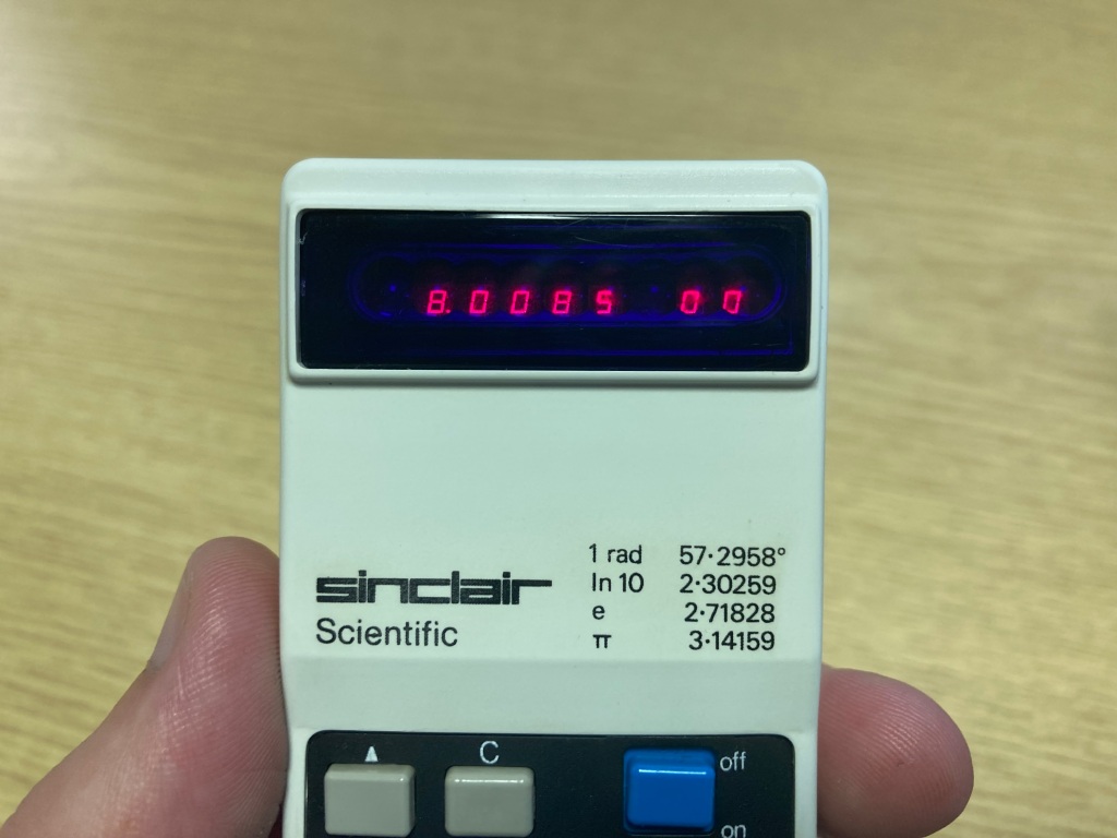
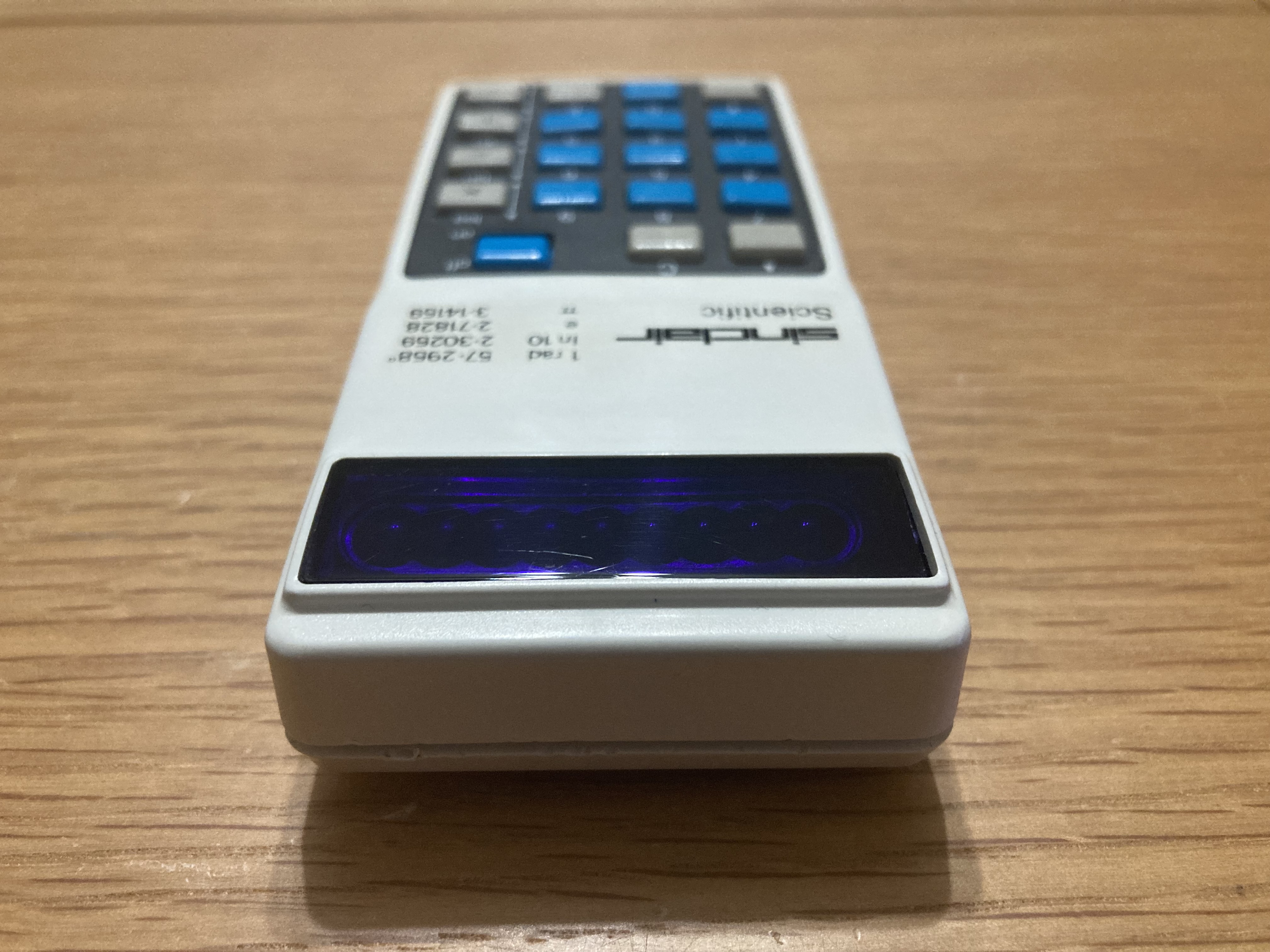
It’s difficult to describe how pretty the LED-segment bubble display on this calculator is – photos don’t quite do it justice. I’ve taken a video of it in the dark, if you’re interested.
After all this work was performed, I did some finishing up: I thoroughly cleaned the case inside and out using Cillit Bang general-purpose degreaser, a microfibre cloth for large areas, and a toothbrush for small areas; I also found that baking soda worked very well for removing the staining on the case, presumably from it being handled, though I had to take lots of care so as not to damage the printed lettering on the case.
The calculator seemed to work OK, but thorough testing is necessary to verify correct operation, so I did as much testing as I could.
- Calculator powers on OK.
- Power switch works well
- All buttons work correctly.
- All display segments work well.
- All calculator functionality seems to work OK.

Another restoration complete, and my first vintage calculator saved!


Hi Adam, Although I didn’t understand much of this post, I did find it extremely interesting. I salute your persistence in getting the calculator(s) to work. Well done! Geoff
Sent from our iPad
>
LikeLiked by 1 person
Hi Geoff, I hope you’re well 😊 Thanks for the feedback, I’m very glad that you enjoyed the article! I’m very pleased with the end result – many thanks again for sending the calculator my way 😊
LikeLike
I thoroughly enjoyed reading this. I’m not great with troubleshooting electronics, so it was great to see how you broke everything down. It’s a pity the first board is dead, but you did a heck of a job getting it into almost original condition. Sinclair cut corners everywhere, so it’s amazing to think that an almost 50 year old calculator could be restored.
LikeLiked by 1 person
Thank you very much, I’m glad you enjoyed it 😊
LikeLike
Nice work. Automatically replacing electrolytic capacitors in anything that’s more than 20 years old is a good idea. Electrolytics dry out and turn into resistors over time. They are easy to find (Mouser, Digi-key) and cheap, and their values, especially in power supplies, are rarely critical..
LikeLiked by 1 person
Thanks for such an informative write up. Coincidentally, I was looking through some scans of old electronics magazines from the mid 70’s that I used to own in paper form. The advertisements are now some of the more interesting pages and I remember the Sinclair calculator, but I was in school and such luxuries were beyond my means.
Have you done any calculations using the scientific functions and compared results with more modern machines?
LikeLiked by 1 person
Thank you, I’m glad you liked it 😊 I haven’t to be honest, though I am tempted to now that you mention it. If you’d like to give it a go yourself, Ken Shirriff has made an accurate Sinclair Scientific emulator: http://files.righto.com/calculator/sinclair_scientific_simulator.html
LikeLike
An interesting read. Got my Sinclair Scientific from my parents as a reward for passing O-Levels (1975!). I recall that occasionally on power-up the display would just start counting up from 1, reboot to stop this. Never reproducible on demand – fault or feature, could never tell.
LikeLiked by 1 person