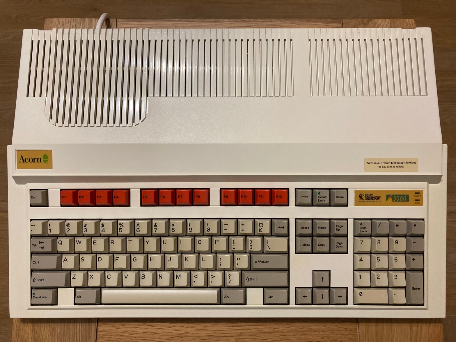
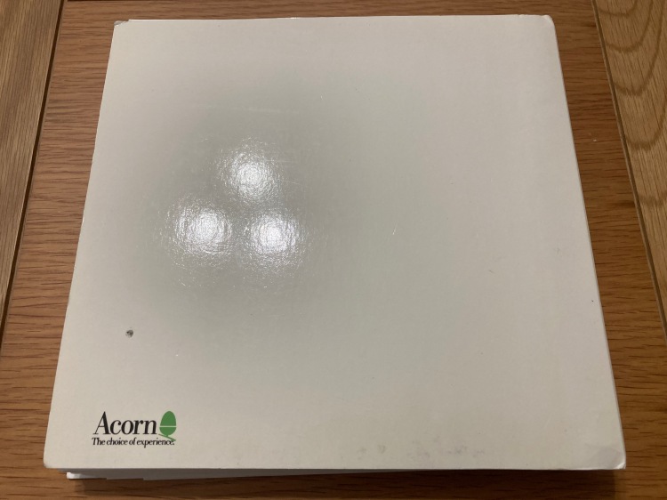
I recently acquired my first Acorn Archimedes 3000, yet another vintage computer to add to my collection. The machine was in very good condition and came with several accessories and its original box, as well as a matching Acorn AKF-17 CRT display, however it was bought sold-as-seen.
The Acorn Archimedes 3000, or A3000, was released in May 1989 to replace the Acorn 300 series, and is reported to be the first home microcomputer to use SMD technology in its construction. The A3000 featured an 8 MHz 32-bit ARM2 CPU, 1 MB of RAM (expandable up to 4MB), and RISC OS 2 (upgradable to RISC OS 3) on 512 KB of ROM. Unlike the previous models, the A3000 came in a single-part case similar to the Amiga 500 and Atari ST, with the keyboard, disc drive, and power supply integrated into the base unit.
The A3000 had good sales in the UK and was used in a lot of educational establishments as a part of the BBC’s Computer Literacy Project, so they are not too difficult to find – there are usually a few up on eBay at any one time, but they often command high sale prices.


The machine was “sold-as-seen” for spares/repairs – the previous owner claimed that the computer started up into the supervisor, and gave a “keyboard not present” error. I figured that because the machine was partially working, it would likely be repairable.
Unfortunately, the A3000 (and other machines of the era with a battery-backed RTC, such as the Amiga 500+) have Varta rechargeable nickel-cadmium batteries soldered to the mainboard which leak a corrosive alkali (potassium hydroxide), even during storage.
This corrosive material is notorious for killing machines because it eats away at the PCB, causing damage to ICs, sockets, traces, vias, connectors, and components. These types of batteries should therefore be removed and disposed of as soon as possible.

As such, I didn’t even attempt to power up the computer in its current condition. Instead, I opened the computer for inspection, which is a relatively simple procedure as the case is only held together with three clips and three screws.


After removing the keyboard, internal 3.5″ FDD, 1MB RAM expansion, and PSU connections, I found that the damage was (luckily) limited to the battery area itself, between the keyboard connectors (top-left) and the ROM sockets (middle-right).


This is the only A3000 that I’d worked on at this point, but in comparison to other examples posted online (which ranged between no damage whatsoever, and nearly-irreparable chaos) this seemed like a moderate case of corrosion. Given that the machine was allegedly partially working, I figured it should be repairable, so I set about cleaning up the battery leakage.
Past this point I’d recommend wearing a set of nitrile gloves, and cleaning your hands, tools, and workspace regularly, as battery alkali is pretty nasty stuff.
I removed the board for improved access, which also allowed me to inspect the underside for further damage – the board is only held in place with three screws, and the metal backplate is held on with the six hex screws on the rear ports.


The first step was to remove the source of the corrosive material: the battery itself. I used a small pair of clippers to cut its three legs close to the PCB, taking care not to cause damage to the board – then, I pulled it off and put it straight in the bin. In this case, the negative terminal had completely corroded away.


The second step was to neutralise the remaining corrosive material. I removed the four socketed ROM ICs and bathed the affected area in white vinegar for a while to neutralise the battery alkali, scrubbing it gently with an ESD-safe brush to make sure that the acid reached as much of the space as possible – then, I washed the board off with 99.9% IPA to remove the leftover alkali salts and vinegar, again scrubbing gently. I left the board to dry and carefully disposed of the vinegar and IPA solutions.


The third step was to do an initial inspection and clean-up of the battery damage. The four ROM sockets had only minor corrosion, but I decided to replace all four anyway – I removed these and the leftover battery legs using my desoldering station (a Duratool D00672) and a large amount of leaded solder and rosin flux, necessary because the corroded material on the affected solder joints makes them difficult to work on.

I carefully scraped away the corrosion on the battery vias and any suspect solder mask on the surrounding traces, then tinned any bare copper with solder so it was easier to spot any copper damage. After doing so, there were two obvious breaks – one on each of the battery terminals – which I jumped with wrapping wire.


I then installed a new set of 32-pin ROM sockets and re-fitted the original ROM ICs – I also installed a CR2032 battery and holder, which is a direct replacement for the original battery and features a built-in diode to prevent back-charging. I opted for this over a soldered rechargeable NiMH battery because coin cells are very easy to remove or replace – the original battery was a 1.2V 280mAh alkali cell, but the PCF8583P CMOS RAM chip used by the A3000 accepts a wide supply voltage range (1V to 6V), so a large number of suitable replacement batteries are available.
I always use high-quality double-sided sockets, which are more reliable than cheap single-sided sockets as they contact the IC legs on both sides – a lot of people push the use of turned-pin sockets, but I don’t like using them as they make swapping ICs difficult, they are difficult to desolder, and they are visibly obviously non-standard.

I cleaned any leftover corrosion on the nearby IC legs and the mouse and keyboard sockets as best I could, then cleaned the keyboard sockets with contact cleaner – they looked a little worse for wear, but I decided to keep the originals for now.


I reinstalled the mainboard for initial testing, now that the obvious damage was cleaned up – I connected the machine up to a suitable display and turned it on, but instead of booting into the RISC OS 2 desktop as it should, it started up into the supervisor giving a “no keyboard present” error, and none of the status LEDs worked.

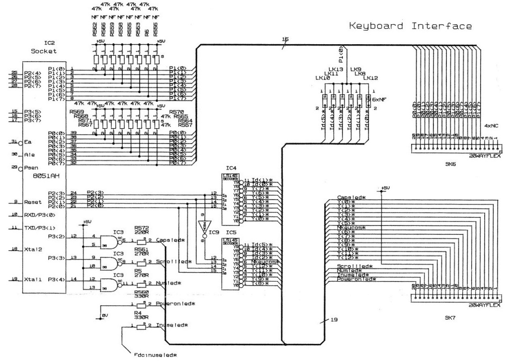
The “no keyboard present” error indicates a problem with the keyboard circuit (see below), either a connection issue with either of the two membrane tails, or a logic issue – potentially with either of the 74LS145s at IC4 and IC5, used for decoding, or the 74HC74 at IC47, used to generate the keyboard clock.
Given that neither of the status LEDs on the keyboard were working, I figured that this was probably a contact issue – therefore, I removed and replaced the original keyboard sockets, and trimmed down the ends of both of the keyboard membrane tails, which had minor corrosion. I also removed the mouse connector and all of the DIP ICs in the area, both so I could test them and so I could clean up any corrosion underneath.


After thoroughly cleaning the area, I noticed that one of the vias underneath IC5 was particularly corroded, so I installed a wire jumper through it.
It seems that the vias on this mainboard version are particularly vulnerable to corrosion as they are not filled with solder, so corrosive material can seep in and dissolve them from the inside out – this is a continued theme, as you’ll see later on.

I reinstalled the original mouse connector, after soaking it in white vinegar for a few hours; I installed two new keyboard connectors; I installed sockets on the DIP ICs that I’d removed; although the both 74LS145s and the 74HC74 tested OK using my MiniPro TL866II, I decided to replace them with new parts as they were quite corroded; I refitted the original 8583 CMOS RAM IC, as I didn’t have a replacement to hand.
I also decided to upgrade the machine from RISC OS 2.x to RISC OS 3.11, which involved fitting a set of RISC OS 3.11 ROMs and setting the ROM size jumpers correctly.
I also installed a serial port upgrade, which involves populating the two empty sockets at the top-left of the mainboard: one is for an LTN1133ACN line driver IC, and the other is for a 65C51 ACIA controller IC, neither of which were fitted from the factory.


I set the machine back up again for testing, and powered it back up – this time, it still booted up into the supervisor but without a keyboard error, all of the keyboard keys worked (including the latched keys, such as shift lock), and all the status LEDs worked.

However, the machine wouldn’t boot into the desktop, and instead provided a power-on self-test (POST) error code through flashing the FDD activity LED at startup – the specific code was “0000 0000 0000 0001 0000 0000 0000 1001”, which indicated that the CMOS RAM was not readable. This is a common fault caused by battery damage, and means that the 8583 CMOS RAM IC has failed or is not connected properly.

I had already socketed the 8583 IC, so I fitted a replacement in case the original had failed, however there was no change in symptoms, indicating a connection issue.
The 8583 IC is driven via I2C from IC13 (IOC), where IOC pin 44 (C<0>) is 8583 pin 5 (SDA) and IOC pin 45 (C<1>) is 8583 pin 6 (SCL) – I tested continuity between these, but both were open-circuit. On further inspection, I noticed that some of the traces and vias under and around the 8583 IC were worse than I originally anticipated.


I removed the battery and 8583 socket that I’d installed so I could get a better look, then further cleaned off the solder mask and tinned any suspect areas – this showed quite clear damage to four vias under and around the 8583, and further damage to the trace leading to the battery positive terminal.

I installed wire jumpers through each of the suspect vias; I also jumped the battery terminals in a more secure and reliable manner.

Then, I reinstalled the 8583 socket and IC, and the replacement battery holder.
The damaged SMD pads on the underside of the battery area are for keyboard pull-up resistors, which are not fitted from the factory so don’t serve a purpose.


I had removed the electrolytic capacitor at C15 to check for corrosion underneath, and I didn’t want to reinstall the original as it could have been affected by the battery alkali, so I fitted a new part. I also figured that if I was replacing one electrolytic capacitor, I may as well replace them all (the radial ones, at least) for preventative maintenance.
Electrolytic capacitors are commonly used for filtering, smoothing, and decoupling in both high- and low-voltage electronics. They typically comprise aluminium windings which are coated with a liquid electrolyte, which can dry out over time (negatively affecting the performance of the capacitor, often causing them to fail dead-short), or leak out and cause corrosion to the PCB and surrounding components.
The A3000 was manufactured using through-hole electrolytic capacitors – being an established technology for the time, these capacitors are generally reliable and rarely cause problems. However, in this case the previous battery leakage may have compromised their performance, so I replaced them out of caution.
I usually remove each capacitor one-by-one using my desoldering station (a Duratool D00672) and immediately install a replacement, taking particular care to ensure that the value, voltage rating, and orientation of the new capacitor are correct – electrolytic capacitors are polarised, so must be installed the correct way around, else they’ll cause problems later (potentially even blowing up during use). I then clean up all the remaining flux residue or heat marks using 99.9% IPA.
You can’t always trust the markings on the PCB silkscreen, as sometimes mistakes were made in the design from the factory (take the PCB layout of the audio circuit on the Commodore CD32, for example), so care must be taken to match the orientation of the new capacitor with the original.
I couldn’t find any commercially available capacitor packs for the A3000, so I just made up my own by noting the specifications of all of the radial electrolytic capacitors on the board, and ordering a set of high-quality Panasonic-brand 105C-rated parts.
This was a total of:
6 x 220uF 16V (radial)
2 x 100uF 25V (radial)
4 x 47uF 25V (radial)
8 x 10uF 16V (radial)
1 x 4.7uF 63V (radial)
Please note that this list will likely change between mainboard revisions, so can’t necessarily be relied upon for your own A3000– if in doubt, check.
I didn’t replace the axial capacitors at this time because they were period-correct, very-high-quality, Panasonic metallic parts.


I set the machine back up for testing, and powered it on (whilst holding the delete key, to erase the CMOS) – this time, it booted correctly into the RISC OS 3 desktop!


I hooked up an Archimedes 3-button mouse for in-depth testing, as the desktop isn’t really usable without one. Unfortunately, the mouse up and down directions didn’t work – this wasn’t really a big surprise as the mouse traces run by the battery area and they are very thin, so this was probably a signal continuity problem.

The mouse socket is connected to the rest of the board through nine “links”, or wire jumpers (in this case, zero-Ohm resistors) – two of these are for power (0V, +5V), and seven of these are for signals (four directions and three switches). These signals are interpreted by the 8051 IC at IC2 – there is also a footprint for an auxiliary mouse connector, which is not fitted on this board.
I checked the continuity of the resistors themselves, and they seemed okay – I desoldered all nine so I could more easily inspect the traces in the area.
I then checked continuity of each signal between the mouse socket and the 8051 IC, and I found three lines with no connection: the Yd line, between the mouse socket (SK1) and its wire jumper (L14); the Sw<1> line, between its wire jumper (L13) and the 8051 (IC2); the +5V line, between the mouse socket (SK1) and its wire jumper (L6).
The auxiliary mouse connector had even more open-circuit traces between it and the 8051 IC, probably because most of these run along the upper side of the board and are right next to the battery – however, as this is not used (or even fitted), I didn’t plan on reinstating it during this restoration.
I tracked down the problems on each of these lines by tracing them away from a known-good point, either at the mouse socket or their respective wire jumper.
The Yd line had one damaged trace and one damaged via, both right next to the negative side of the battery, which had to be jumped; the +5V line had one damaged via, near the mouse socket, which had to be jumped; the Sw<1> line had three damaged vias, scattered throughout the battery area, which had to be jumped.


I then reinstalled the resistors into the link points, after cleaning them up.


I tried to keep the repairs as inconspicuous as possible by limiting the lengths of the jumper wires, and using existing traces where possible, otherwise following their original path closely. I think it’s quite a neat repair, and I’m pleased with the results.


I reinstalled the mainboard in the case for continued testing.


The A3000 still booted correctly into RISC OS, and the mouse was now fully working!


Now that I could load from the 3.5″ internal FDD, I cleaned the read/write heads using a head cleaning disk, in case the drive was dusty or dirty. I then tested the internal drive using a couple of system disks, and it seemed to be working fine.


After all this work was performed, I did some finishing up: I thoroughly cleaned the mainboard with compressed air and an ESD-safe brush; I thoroughly cleaned the case inside and out using Cillit Bang general-purpose degreaser, a microfibre cloth for large areas, and a toothbrush for small areas; I also disassembled and cleaned the keyboard.


The computer still seemed to boot OK following all of my modifications. However, just because a computer boots, that doesn’t mean it’s working properly. Thorough testing is necessary to verify correct operation, so I did as much testing as I could.
- All keys register correctly.
- Internal 3.5″ FDD reads and writes from/to disks OK.
- RGB video output works OK.
- Composite video output works OK.
- Stereo audio output via internals speakers works OK.
- Dedicated headphone output works OK.
- All mouse inputs (four directions, three buttons) work OK.
- Internal 1MB RAM expansion works OK.
- Onboard battery-backed RTC works OK.
- Status LEDs (power, drive activity) work OK.
- Serial interface works OK.
- Reset button works OK.

Another restoration complete, and another Acorn Archimedes 3000 saved!


Fantastic article and hats off to you, great detail and a joy to follow. You must get a lot of satisfaction from a refurb like this. I recently dug my old A3000 out and I have the same issue you had with your monitor – the on button doesn’t stay in so I’ve got to hold it in to keep it on – it’s surprisingly resistant to being held in by selotape or duct tape! I’d also previously had the battery replaced with a CR2032 housing and managed to get that done before the Varta exploded. Keep up the posting.
LikeLiked by 1 person
Thanks Steve, I appreciate it a lot 😊 Yes, it was very satisfying indeed to be able to get everything up and running again, and to have a fully-functioning A3000 and monitor! I’m glad to hear that your A3000 has been saved from the dreaded Varta, too. I’ll be doing some more posting in the near future, I’ve been keeping myself plenty busy with my restorations. All my best wishes 😊
LikeLike
Hey Adam.I’ve just recently pulled out my childhood A3000 which is in a similar state.Do you offer a repair service by any chance?
LikeLiked by 1 person
Hi Harris! I’ll drop you an email.
LikeLike
You say that you didn’t replace the axials because they were typically reliable. When I restored an A3010 they were the only capacitors that had fallen way out of spec. It is worthwhile at least testing them if you have an ESR meter. Although even out of spec I wouldn’t expect it to have a huge negative effect until they fail completely.
LikeLike