
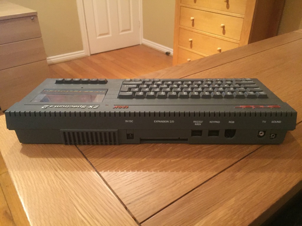
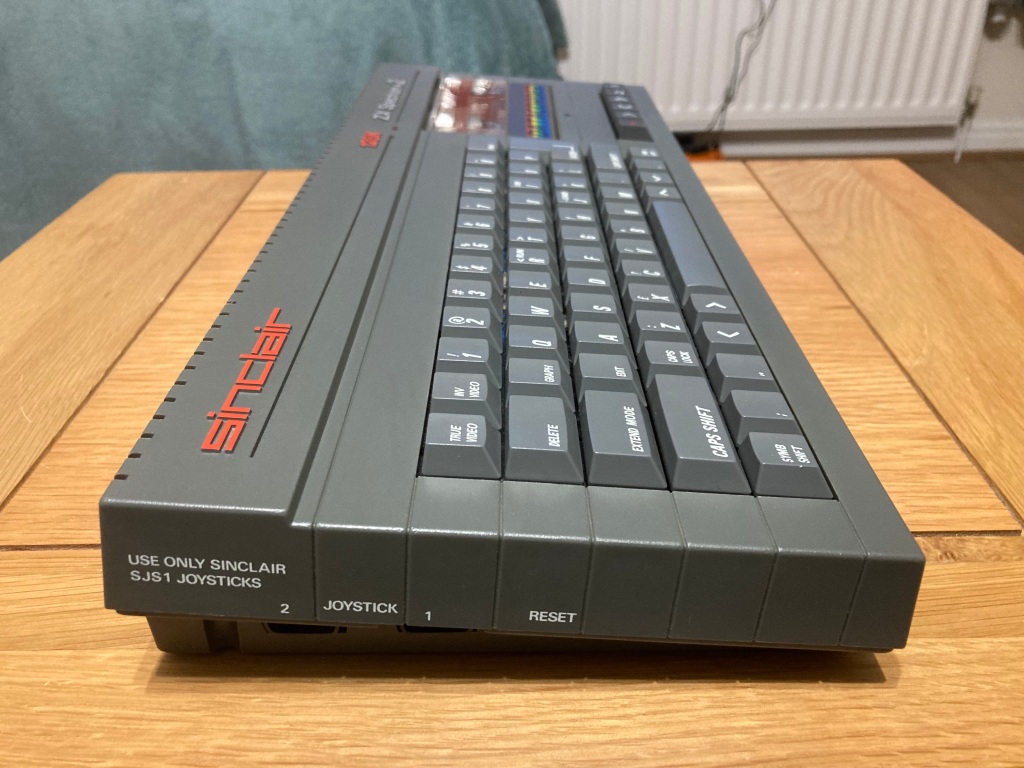
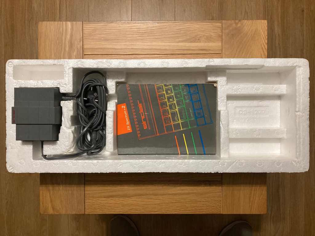
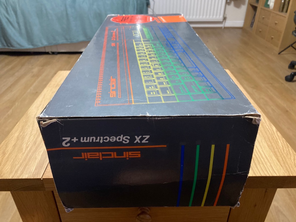
A while back I got my hands on my first Sinclair ZX Spectrum 128k+2 (grey), yet another 1980s 8-bit computer to add to my collection. The machine was in good condition and came with several accessories and its original box, however it was sold as “untested”.
The Sinclair ZX Spectrum 128k+2 was the first machine produced by Sinclair following their takeover by Amstrad, and was a replacement for the ZX Spectrum 128k+ – the 128k+2 was a quick and crude redesign of the 128k+ hardware but in a larger and re-styled grey case, featuring an internal tape deck similar to the Amstrad CPC 464.


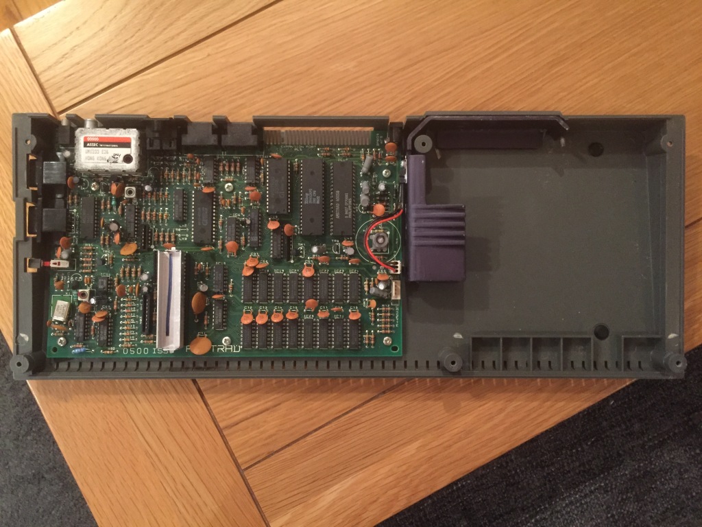
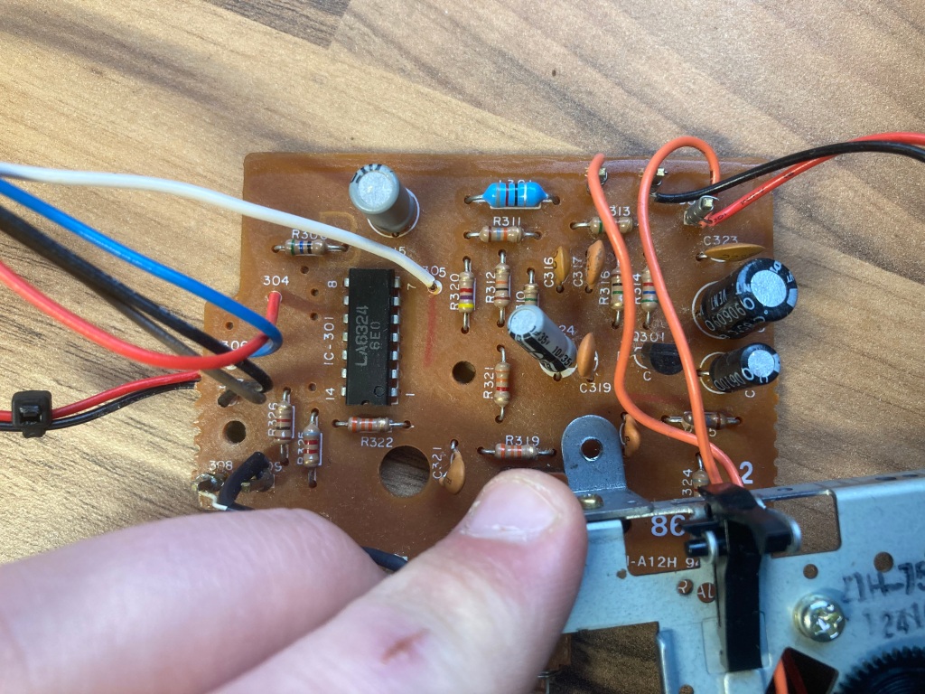
The Spectrum seemed to be all original, and featured a 1986 Z70500 ISS3 mainboard with 128 KB of factory-installed RAM – the ULA, CPU, and ROM were socketed.

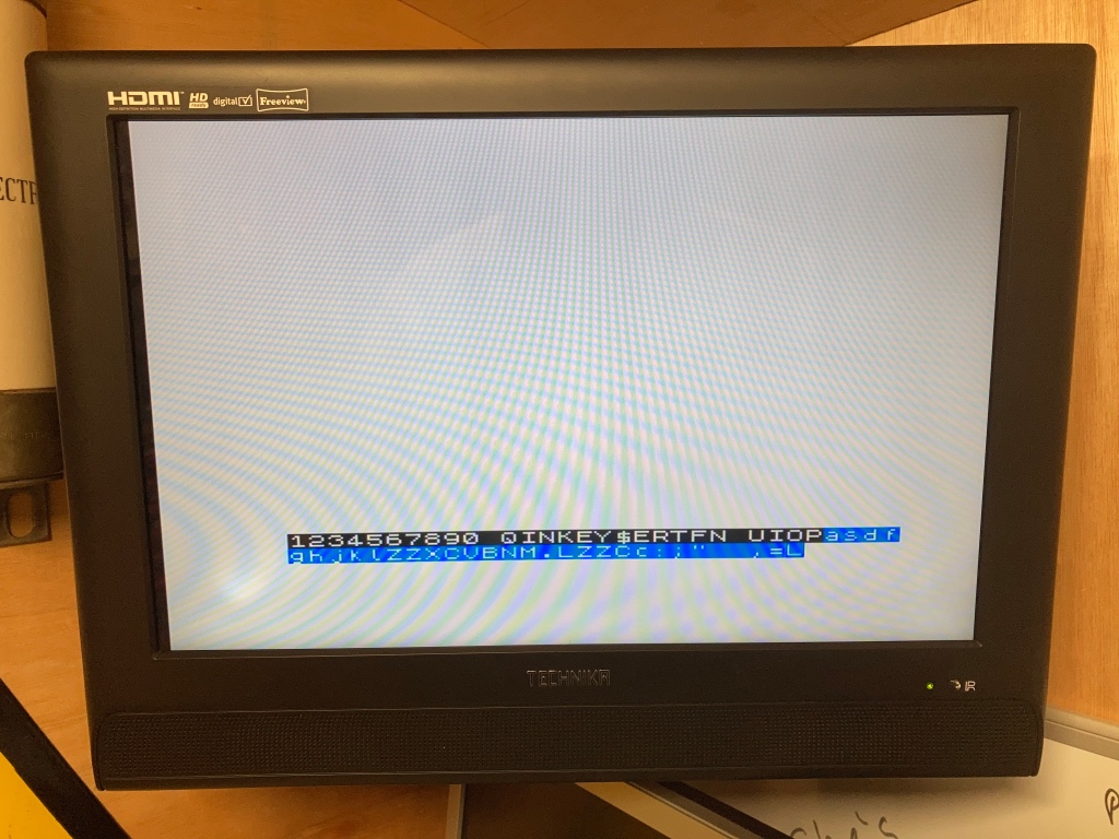
After checking that the PSU was working OK, I did a quick power-on test plugged into the composite video port and the computer seemed to boot up fine.

There are several steps which I like to take when performing a complete restoration on a Spectrum, which include fixing factory or age-related problems, and future-proofing.
As such, I planned out the servicing, preventative maintenance, and upgrades that I wanted to perform, as follows:
#1: Fix the video output issues associated with the factory ZX Spectrum 128k+2.
#2: Fix the audio balancing issues associated with the factory ZX Spectrum 128k+2.
#3: Replace all the electrolytic capacitors on the mainboard and tape board.
#4: Replace the voltage regulator and power connector.
#5: Service the internal tape deck.
#6: Refurbish the power supply.
#1: Fix video output issues:
The ZX Spectrum 128k+2 (and upon extension the 128k+, its predecessor) suffer from various design flaws which affect their video quality.

Firstly, the Z70500 ISS3 mainboard has a major design fault where three 2N3904 transistors (TR4, TR5, and TR7) are marked incorrectly on the PCB silkscreen and, as such, were installed backwards at the factory.
TR4 is part of the composite video circuitry, TR5 is responsible for generating the RGB vertical sync, and TR7 is responsible for generating the ULA IOREQ signal, so having all of them reversed causes serious video problems.
There is a lot of speculation as to why this error occurred – either the transistor type was swapped to 2N3904 at some point and the silkscreen was not updated, or the designers were working with an incorrect version of the 2N3904 datasheet.
I removed all three offending transistors and replaced them with new parts, which I installed the correct way around (opposite to the silkscreen). After doing this, the quality of the composite video signal was greatly improved, but still had a lot of interference patterns.
Secondly, the audio signal is not only attached to the RF output, it’s attached much earlier in the video chain – this leads to video distortion on the composite video output. By disconnecting the output of C31 and reattaching it to the emitter of TR1 (via R4), the audio signal will be removed from the dedicated video outputs, but will still be available on RF – this leads to a very significant quality improvement.
On some earlier boards (such as the Z70500 ISS3), C31 is on the underside of the board, under the TEA2000 – on later boards, it is on the component side.
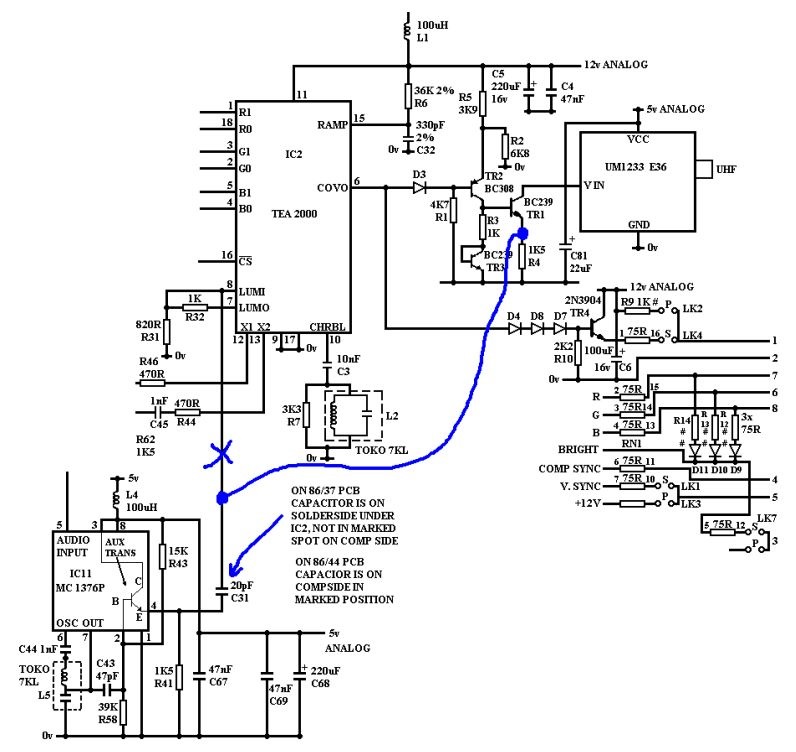
Finally, the composite video signal filtering on the Spectrum 128k+2 is poorly designed and causes ghosting – by disconnecting the factory LC filter by removing C3, this effect is reduced. Also, an optimised LC filter can be installed to reduce ghosting even more – this involves installing an 87pF capacitor in series with a 15uH inductor between pin 8 of TEA2000 and GND, which I did on the underside of the PCB.

Another method of improving the video quality on 128k+2 machines (specifically, to reduce the “jailbar” effect on the background) is to increase the filter capacitance on the 12Vdc power rail, by replacing C52 with a 100uF electrolytic capacitor and replacing C72-C79 with 1nF ceramic capacitors. I did not perform this modification, as I didn’t notice any jailbar effect on either composite or RGB video.
Some displays may not work correctly with the factory grey +2 via RGB SCART, due to an issue with the SCART blanking signal this can be corrected with some minor modifications to the links and resistors near the video socket on the mainboard. I did not perform this modification, as all of my displays seem to work OK with the +2.
#2: Fix audio balancing issues:
Sinclair machines are well known for their quality issues, both in design and manufacture, and the 128k+2 is no exception – design errors in the audio circuitry (specifically the balancing stage) cause the 3-channel audio from the AY-3-8912 chip to be significantly quieter than the beeper audio from the ULA.
The audio from the internal tape deck is also extremely loud, leading to an annoying “buzzing” sound in the background constantly.
It is possible to amend this issue – I won’t cover this process in a lot of detail, as this is already documented online, but it involves replacing some resistors with different values between the various audio sources to try and equalise the balance properly:
- R80 (EAR to audio output): 10k on schematic, replace with a 330k 0.5W part.
- R45 (MIC to audio output): 10k on schematic, replace with a 39k 0.5W part.
- R37 (AY soundchip audio output): 10k on schematic, replace with a 3.3k 0.5W part.
- R38 (RF audio output): 10k on schematic, replace with a 5k6 0.5W part.


Once installed, this increases the level of the AY generated audio so that it is now only slightly quieter than the ULA/cassette generated sounds. This is most noticeable on 128k games that use the AY sound chip, such as Robocop.
Here are some before and after videos of the audio output. Much better now!
#3: Replace all the electrolytic capacitors on the mainboard:
Electronic components generally don’t “age” as such, except for electrolytic capacitors, which are commonly used for filtering, smoothing, and decoupling in both high- and low-voltage electronics.
These capacitors typically comprise aluminium windings insulated by a liquid electrolyte, which can dry out over time and negatively affect performance (even failing dead short), or leak out and cause corrosion to the PCB and surrounding components – as such, they should be replaced as a part of preventative maintenance.
As such, I always replace all the original electrolytic capacitors with high-quality modern equivalents, which usually substantially improves the video quality. This takes some time on the Spectrum 128k+2 as there are several capacitors and the board can be quite fragile, so care should be taken – there are also capacitors on the cassette deck board which need to be replaced, which can be rather fiddley.
I usually remove all of the capacitors at once using my desoldering station (a Duratool D00672), then install the new ones one-by-one whilst taking particular care to ensure that the value, voltage rating, and orientation are correct – electrolytic capacitors are polarised, so must be installed the correct way around, else they’ll blow up during use.
You can’t always trust the markings on the PCB silkscreen, as sometimes mistakes were made in the design from the factory (take the Commodore CD32, for example), so care must be taken to match the orientation of the new capacitor with the original.
I used a commercially available capacitor pack from Retroleum.


The tape deck daughterboard also has electrolytic capacitors, which I also replace whilst recapping +2 mainboards. This is sometimes possible to do with the tape deck installed in the case, but if the head cables are to short, you might need to remove the tape deck – this is easy to do, as it is only held in place by five cross-head screws.

#4: Replace the Power Connector & Voltage Regulator:
I/O ports and edge connectors on computers see a lot of use which can mean that they get loose and unreliable, and they can corrode during use or in storage.
As such, I always install a new power connector (a 2.1mm DC jack), which can be bought new from Retroleum. I also carefully clean both sides of the edge connector with a white eraser, and clean all of the I/O ports and IC sockets with contact cleaner.
I also decided to replace the original 78S05 5Vdc linear regulator, which is inefficent and requires a large heatsink, with a modern 2A-rated switching equivalent, which runs cool – I desoldered the pin header on the mainboard for the original 78S05, and installed the new TSR 2-2450 directly onto the mainboard.
#5: Service the internal tape deck:
The ZX Spectrum 128k+2 has an internal cassette deck, which uses standard analogue cassette tapes. These decks are belt-driven, and use a rubber belt which is particularly prone to ageing – even if the belt looks OK, it could have stretched or deformed with age, causing cassette loading to be unreliable or impossible.
The deck can be serviced in-situ, and does not have to be removed from the case – this involves replacing the original drive belt, cleaning the read/write heads and pinch roller, and adjusting the head azimuth with a calibration tape.
I won’t cover this process in detail, as it is already documented online.

#6: Refurbish the power supply:


Functionally, the original PSU was working fine – I always install a modern mains plug (3A fused) on any PSUs that I use, and check the output voltage(s). Aside from that, the PSU casing and cabling just needed a good clean.
I’d usually recommend using a modern PSU with any vintage computer, as the originals can be prone to failure – however, the ZX Spectrum takes an unregulated 9 Vdc input which is regulated internally, meaning a PSU failure would be unlikely to damage the computer, so an original PSU (with a modern plug) should be safe to use.
It is normal for these unregulated 9 Vdc PSUs to output a voltage greater than specified (typically around 15 Vdc unloaded), even under load, as this will be roughly linear to the AC input voltage – according to its datasheet, the 7805 voltage regulator can output 5 Vdc at up to 1.5A and handle an input voltage of up to 25 Vdc.
Testing and Conclusion
After all this work was performed, I did some finishing up: I thoroughly cleaned the mainboard with compressed air and an ESD-safe brush; I thoroughly cleaned the case inside and out using Cillit Bang and a microfibre cloth; I also replaced the thermal compound on the ULA heatsink.
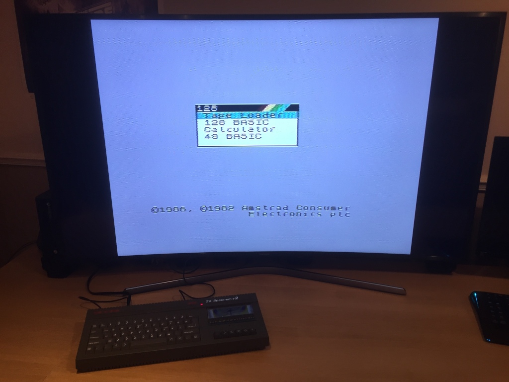
The computer still seemed to boot OK following all of my modifications. However, just because a computer boots, that doesn’t mean it’s working properly! Thorough testing is necessary to verify operation, so I did as much testing as I could.
- All keys register correctly.
- RGB and composite video outputs work OK (RF untested).
- Internal tape drive works OK.
- Power LED works OK.
- Reset button works OK.
- Expansion port works correctly with DIVMMC Future.
- 128k ROM/RAM tests pass OK (soak tested for 2 hours).
- 48k beeper audio and AY sound chip audio are clear and well balanced.
- All joystick inputs work.


Another restoration complete – happy days!


Nice work!
LikeLiked by 1 person
Thank you 😊
LikeLike
This is a godsend! I’ve been messing around with my 128 +2 (iss3) for quite a while trying to figure out why the video doesn’t seem to work. Never would have dawned on me that there were transistors installed incorrectly from the factory (with incorrect silkscreen)!
LikeLiked by 1 person
Thank you, I’m very glad that it’s helped you out 😊
LikeLike
Nice job. I have great memories of the 128k+2. My first experience of computers. You clearly know your components.
LikeLiked by 1 person
hi i did all the mods to my sinclair i even upgraded the filer cap on the psu ,the only thing i did not do was replace the voltage regulator 78S05 ,but i have a audio buzz ,and yess i did the audio resistor mod ,so the buzz is coming from the tape
LikeLike