
A while back I got my hands on my first Sinclair ZX Spectrum 48k “rubber key”, yet another 1980s 8-bit computer to add to my collection. The machine was in very good condition and came with several accessories as well as its original box, however it was sold as “untested”.
The Sinclair ZX Spectrum 16/48k was one of the early machines produced by Sinclair, and was the replacement for the ZX81 in 1982 – the Spectrum was a significant redesign and featured far more processing and graphical capabilities.


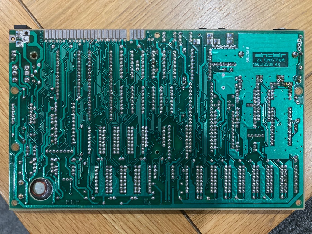
The Spectrum featured a 1984 ISSUE 4B mainboard with 48 KB of factory-installed RAM – the ULA was socketed. It seemed to have been repaired at some point (warranty and test stickers, a socketed upper RAM IC, new electrolytic capacitors, and solder flux residue on the underside of the CPU and ROM), and had a weird cable coming out of the case from under the “mic” socket.


The first thing I did was clean the board and remove the weird cable coming from the case, which was presumably for some form of audio input.

At the time of this restoration I didn’t own an old TV with an RF input, so I’d have to modify the machine before I’d be able to test it.
There are several steps which I like to take when performing a complete restoration on a Spectrum, which include fixing factory or age-related problems, and future-proofing.
As such, I planned out the servicing, preventative maintenance, and upgrades that I wanted to perform, as follows:
#1: Modify the RF video output to display composite video instead.
#2: Replace the original voltage regulator with a modern switch-mode equivalent.
#3: Replace the original connectors with new parts.
#4: Replace all the electrolytic capacitors on the mainboard.
#5: Replace the original keyboard membrane.
#6: Refurbish the power supply.
#1: Composite video modification:
The Sinclair ZX Spectrum’s only video output is modulated RF via an RCA jack, as it was designed to be compatible with old-school televisions as opposed to expensive monitors – however, this limits its compatibility with modern displays and reduces the quality of the video signal, due to the degradation caused by modulation and subsequent demodulation.
In the Sinclair ZX Spectrum 16/48k/48k+, it is possible to modify the RF modulator to output a composite video signal instead of modulated RF, which offers a much better image quality and is compatible with most modern displays.
Following this guide, I installed a composite video modification neatly and in a professional fashion inside the RF modulator, using a low-profile 100uF 10V electrolytic capacitor instead of a wire jumper – this blocks any DC offset on the video signal, improving display compatibility and reducing power consumption.
This involved removing the lid from the RF modulator, disconnecting the 5V power supply to the modulator PCB, disconnecting the video input to the modulator PCB, disconnecting the RCA jack inner pin from the modulator PCB, and redirecting it to the video input from the mainboard.
You can see my installation below – I’ve done it in a reversible manner, and it is very difficult to tell from the outside that a modification has been performed.


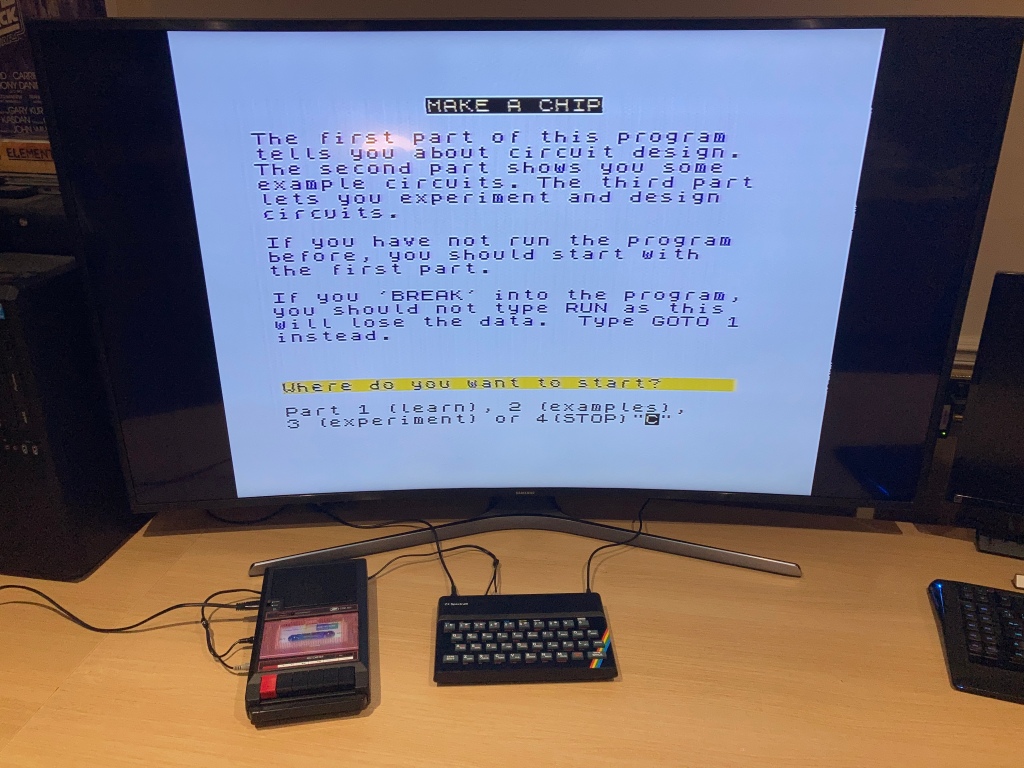
I then re-tested the system, and it now seemed to be outputting a bright, stable, and crisp composite video signal which displayed well on my TV.

#2: Replace the voltage regulator:
From the factory, the ZX Spectrum uses a 7805 linear regulator (attached to the large heatsink at the top of the board) to regulate the 9Vdc input voltage to 5Vdc. Linear regulators are inefficient, unreliable, and produce a lot of heat, particularly under load – this heat builds up inside the case, increasing the interior temperature and subsequently reducing the lifetime of the electronics.
Modern, switch-mode, drop-in replacements for the 7805 are available, such as the Traco Power TSR-2450 – I removed the original heatsink (held in place by a bolt) and desoldered the original regulator, then installed one of these in its place.
#3: Refurbish the I/O (ports, edge connectors, etc):
I/O ports and edge connectors on computers see a lot of use which can mean that they get loose and unreliable, and they can corrode during use or in storage.
As such, I always install a new power input jack (a 2.1mm DC jack) and new “ear” and “mic” connectors (both 3.5mm mono jacks), all of which can be bought new from Retroleum. I also carefully clean both sides of the edge connector with a white eraser, and clean all of the IC sockets with contact cleaner.


#4: Replace all the electrolytic capacitors on the mainboard:
Electronic components generally don’t “age” as such, except for electrolytic capacitors, which are commonly used for filtering, smoothing, and decoupling in both high- and low-voltage electronics.
These capacitors typically comprise aluminium windings insulated by a liquid electrolyte, which can dry out over time and negatively affect performance (even failing dead short), or leak out and cause corrosion to the PCB and surrounding components – as such, they should be replaced as a part of preventative maintenance.
As such, I always replace all the original electrolytic capacitors with high-quality modern equivalents, which usually substantially improves the video quality – this takes some time on the Spectrum as there are several capacitors and the board can be quite fragile, so care should be taken. In this case, all of the electrolytic capacitors had already been replaced.
I usually remove all of the capacitors at once using my desoldering station (a Duratool D00672), then install the new ones one-by-one whilst taking particular care to ensure that the value, voltage rating, and orientation are correct – electrolytic capacitors are polarised, so must be installed the correct way around, else they’ll blow up during use.
You can’t always trust the markings on the PCB silkscreen, as sometimes mistakes were made in the design from the factory (take the Commodore CD32, for example), so care must be taken to match the orientation of the new capacitor with the original.
Another method of improving the video quality on 16/48k/48k+ machines (specifically, to reduce the “jailbar” effect on the background) is to increase the filter capacitance on the 12Vdc power rail, by installing 220nF ceramic capacitors in place of C5 – C8.
I used commercially available capacitor packs from Retroleum.


#5: Replace the keyboard membrane:
The keyboard in the Spectrum uses a membrane – comprising several plastic layers with printed conductive tracks, which make a contact when a key is pressed – which tends to become brittle with age, and either becomes unreliable or stops working altogether. I always replace these as a matter of course, no matter their condition.
Accessing the keyboard membrane requires dismantling the computer – the ZX Spectrum 48k is relatively simple to pull apart, with five screws on the underside of the case, and two keyboard membrane tails plugged into the mainboard.

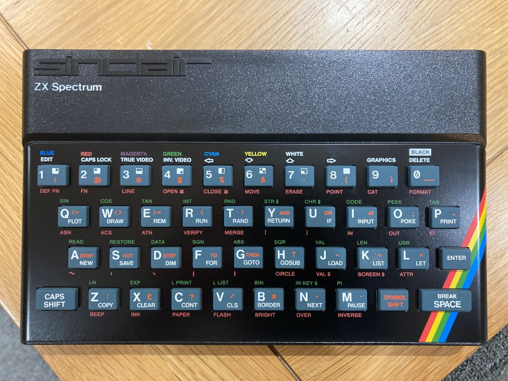
To access the keyboard membrane, the keyboard faceplate (the painted aluminium plate with the key descriptions on) must be removed. There are two types: one with four metal clips holding it to the upper case, and one that is held in place with adhesive. The former is easy to remove, but the latter is difficult to remove without damage.
In this case, the original faceplate was a clip-on type and came off easily – however, it was scratched and quite dull, so I decided to replace it with a modern replica.


Modern-made keyboard membranes are available to purchase from various retailers – take care to buy the correct type, as the early 16/48k “rubber-key” uses a different membrane from the 48k+/128k+. The new membrane can then be installed – I won’t cover this procedure in detail, as it is already documented comprehensively online.

Once the membrane was installed I tested it, and all keys now registered correctly.
#6: Restore the power supply:

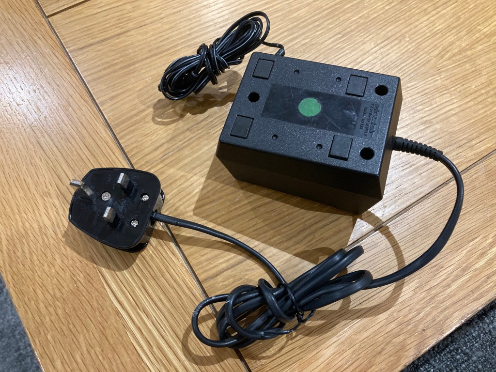
Functionally, the original PSU was working fine – I always install a modern mains plug (3A fused) on any PSUs that I use, and check the output voltage(s). Aside from that, the PSU casing and cabling just needed a good clean.
I’d usually recommend using a modern PSU with any vintage computer, as the originals can be prone to failure – however, the ZX Spectrum takes an unregulated 9 Vdc input which is regulated internally, meaning a PSU failure would be unlikely to damage the computer, so an original PSU (with a modern plug) should be safe to use.
It is normal for these unregulated 9 Vdc PSUs to output a voltage greater than specified (typically around 15 Vdc unloaded), even under load, as this will be roughly linear to the AC input voltage – according to its datasheet, the 7805 voltage regulator can output 5 Vdc at up to 1.5A and handle an input voltage of up to 25 Vdc.
Testing and Repairs
The computer still seemed to boot OK following all of my modifications. However – and I know this well – just because a computer boots, doesn’t mean it’s working properly. Thorough testing is necessary to verify operation.


Initially, the Spectrum would not work correctly with my SD card reader, a DivMMC Future from TFW8b (which I thoroughly recommend, by the way). This is usually due to a partial CPU failure (the lack of a valid M1 signal), which was the case on several 48k’s that I’d worked on previously. Sure enough, after socketing and replacing the original Z80 CPU with a known-good part, the SD card reader worked fine.
There is a lot of speculation as to how this failure occurs – some believe that this was a factory fault and that Sinclair bought part-working Z80s on the cheap, whereas others believe that this is a user fault that occurs when an expansion device is installed incorrectly, shorting the M1 line to 12V.
Zilog Z80 CPUs are still manufactured today, so it’s not hard to get hold of them.
Whilst I had the mainboard removed, I also decided to socket the ROM to make the board look more uniform, and I also de-socketed the U17 4164 RAM IC (a “Tesla” part, which I’ve never heard of) and installed a Texas Instruments part in its place, again to make the board look more uniform.
The ZX Spectrum has an unusual RAM configuration: 16KB of “lower RAM” for page and display memory is made up by eight 4116 DRAM ICs; 32KB of “upper RAM” for BASIC memory is made up by eight 4132 DRAM ICs. Sinclair bought 4132 RAM ICs because they were cheap – these were re-branded 4164 RAM ICs which had partially-failed factory testing. As such, they can be replaced by 4164 RAM ICs.

With the SD card reader working correctly, I could load some detailed diagnostic software – I usually use ZX Spectrum Dignostics, which validates the contents of the onboard ROM and tests all the onboard RAM, with an optional soak test mode.
Conclusion
After all this work was performed, I tested the system: all keys registered correctly; the composite video worked OK; the internal speaker worked OK; the machine read and wrote correctly from/to an external tape recorder; the machine worked correctly with the DIVMMC Future; all 48k ROM/RAM tests passed OK; all joystick inputs worked OK.
The case needed a new set of four rubber feet, which are available to purchase on Retroleum – aside from that, it cleaned up really well with a good scrub using Cillit Bang and a microfibre cloth, with a toothbrush to get into all the nooks and crannies.


Another restoration complete – happy days!


Lovely write up and a great result! Thank you for sharing that 🙂
LikeLiked by 1 person
Thank you, I’m glad you think so 😊
LikeLiked by 1 person